
Kia Optima DL3: Manual climate control system / Heating and air conditioning
1. Start the engine.
2. Set the mode to the desired position. For improving the effectiveness of heating and cooling;
- Heating:

- Cooling:

3. Set the temperature control to the desired position.
4. Set the air intake control to the outside (fresh) air position (if equipped).
5. Set the fan speed control to the desired speed.
6. If air conditioning is desired, turn the air conditioning system (if equipped) on.
- Mode selection
- MAX A/C selection
- Temperature control
- Air intake control
- Sunroof inside air recirculation
- Fan speed control, Air conditioning
1. Fan speed control knob 2. Front windshield defroster button 3. Rear window defroster button 4. Air conditioning button 5. Air intake control button 6.
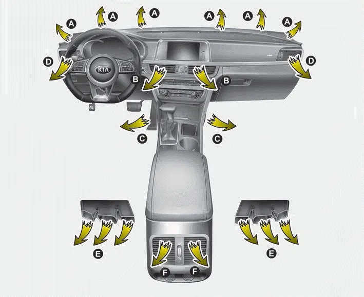
The mode selection button controls the direction of the air flow through the ventilation system. Air can be directed to the floor, dashboard outlets, or windshield.
Other information:
Kia Optima DL3 2019-2026 Service and Repair Manual: Receiver-Drier
Repair procedures Replacement 1. Remove the condenser. 2. Remove the cap (A) on the bottom of the condenser with a L wrench. Tightening torque : 9.81 - 14.71 N.
Kia Optima DL3 2019-2026 Service and Repair Manual: Heater Control Unit
Components and components location Components Connector Pin Function [Connector A] Pin NO Funtion Pin NO Funtion 1 Ground 11 Ground 2 Clean signal 12 -
Categories
- Manuals Home
- Kia Optima Owners Manual
- Kia Optima Service Manual
- Engine Control / Fuel System
- Engine Mechanical System
- Emergency trunk safety release
- New on site
- Most important about car
