Kia Optima DL3: Emergency Call System / Emergency Call (E-call) Unit
Schematic diagrams
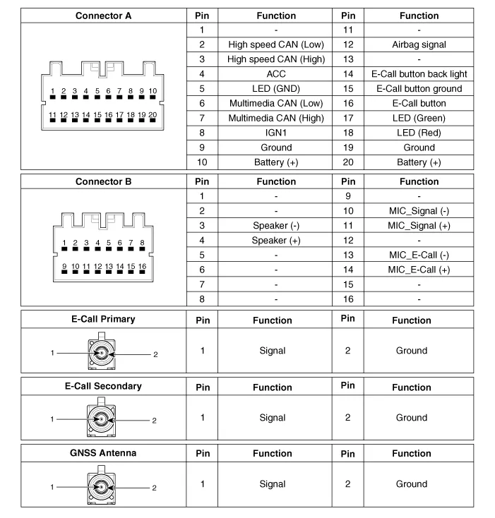
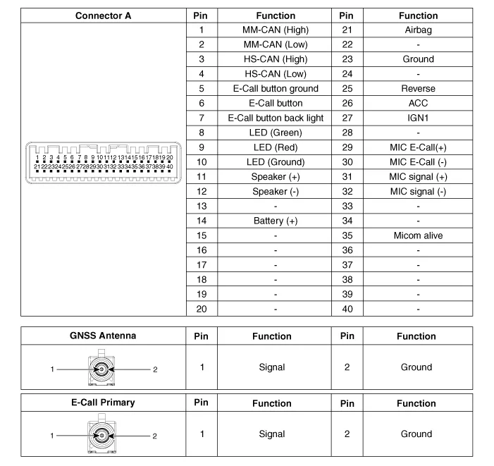
| Connector and Terminal Function |
Repair procedures
E-call Unit
| 1. |
Disconnect the negative battery terminal.
|
| 2. |
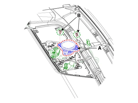
Remove the crash pad center panel.
(Refer to Body - "Crash Pad Center Panel")
|
| 3. |
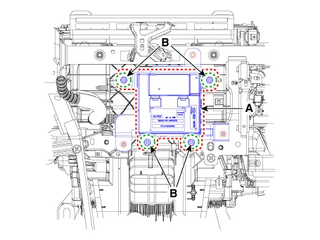
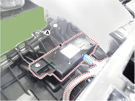
Disconnect the E-call unit connectors.
|
| 4. |
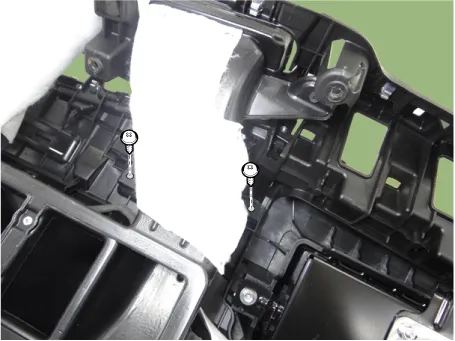
Remove the E-call unit (A) after loosening the mounting nuts (B).
|
E-call Speaker
| 1. |
Disconnect the negative battery terminal.
|
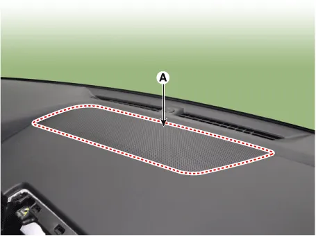
| 2. |
Remove the center speaker grille (A) by using a screwdriver or remover.
|
| 3. |
Disconnect the E-call speaker connector.
|
| 4. |
Remove the E-call speaker (A) after loosening the mounting screws (B).
|
E-call Antenna (Russia
Only)
| 1. |
Disconnect the negative battery terminal.
|
| 2. |
Remove the main crash pad assembly.
(Refer to Body - "Main Crash Pad Assembly")
|
| 3. |
Loosen the E-call antenna mounting screws.
|
| 4. |
Remove the E-call antenna (A) by disconnecting the connector.
|
| 1. |
Install in the reverse order of removal.
|
Perform the Test Mode in the following cases. (Russia Only)
| •
|
Replacing the E-call unit
|
| •
|
Replacing the Back-up Battery
|
| •
|
Replacing the E-call speaker and MIC
|
| •
|
Replacing the E-call antenna and roof antenna
|
|
|
| • |
Back-up battery (BUB) embedded in the E-call system has a finite
lifespan and its charging/discharging performance may be diminished
after an extensive use.
|
| • |
The back-up battery guarantees the operation of the E-call system
when the vehicle battery cannot be used due to an accident. Be sure
to inspect the back-up battery if the red LED turns on and replace
it if necessary.
|
| • |
Warranty on Back-up Battery is 3 years.
|
| • |
Inspect the back-up battery every three years and replace it
if necessary.
|
|
| 1. |
Remove the E-call unit.
(Refer to Emergency Call System - "Emergency Call Unit")
|
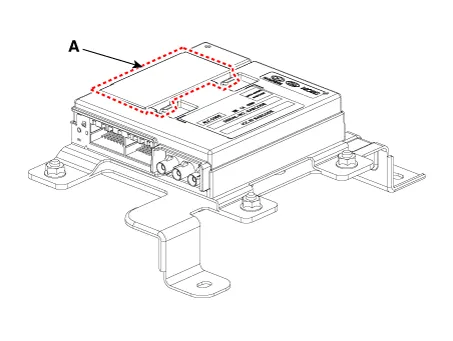
| 2. |
Replace the back-up battery after opening the cover (A).
|
Diagnosis with KDS
| 1. |
In the body electrical system, failure can be quickly diagnosed by using
the vehicle diagnostic system (KDS).
The diagnostic system (KDS) provides the following information.
| (1) |
Self diagnosis : Checks failure and code number (DTC)
|
| (2) |
Current data : Checks the system input/output data state
|
| (3) |
Actuation test : Checks the system operating condition
|
| (4) |
Additional function : Controls other features including system
option setting and zero point adjustment
|
|
| 2. |
Select the 'Car model' and the 'Telematics System' to be checked in order
to check the vehicle with the tester.
|
| 3. |
Select the 'Current Data' menu to check the current state of the input/output
data.
|
E-call Test Mode (Russia
Only)
Press the SOS TEST button to activate the audio guidance and test the E-call
system according to the guidance.
In the Test Call stage, which is the last stage of the test mode, press the SOS
button according to the audio guidance to send the data on faulty components to
the call center.
To stop the test mode, press the SOS TEST button again during the audio guidance.
| 1. |
Conditions for the test mode operation:
| (1) |
Vehicle battery is connected properly.
|
| (2) |
One minute has passed after ignition.
|
| (3) |
The vehicle remains stationary for 1 minute or more.
|
|
| 2. |
Conditions preventing the test mode operation:
| (1) |
A call is made to a PSAP.
|
| (2) |
Call Back mode : The E-call system enters the Call Back mode
after a successful call and is in standby for 120 minutes to receive
calls from the call center.
|
| (3) |
The test mode automatically ends when the vehicle speed is 1
km/h or above or has moved 300 m or more.
|
| (4) |
Two minutes have not passed after the previous test call ended.
|
|
| 3. |
Operation sequence of the test mode (audio guidance):
| (4) |
BUB (Back-up battery embedded in the eCall unit) test (no separate
notification is provided if the BUB is in normal condition.)
|
• |
Backup battery audio prompt guide
|
|
• |
If the audio guidance notifies that "The voltage
of Backup battery is low to make emergency call",
retry test mode after sufficiently charging the
battery by driving.
|
|
|
| (5) |
Test call (Pressing the SOS button sends the test result to a
PSAP.)
|
|
|
The red LED stays turned on if one or more DTCs for the E-call system
are issued.
If the red LED is on, be sure to use the diagnostic tool (KDS) to check
for any failure.
|
Components and components location
Components
1. Supplemental restraint system
control module (SRSCM)
2. Emergency call switch
3.
Repair procedures
Replacement
1.
If the E-Call switch needs to be replaced, replace the overhead console
lamp assembly.
Other information:
Specifications
Specifications
Item
Specifications
Rated voltage
DC 12 V
Operating voltage
DC 9 - 16 V
Operating temperature range
-22 to 167°F (-30 to 75°C)
Dark current
Max.
Repair procedures
Removal
1.
Remove the front seat shield outer cover.
(Refer to Body - "Front Seat Shield Outer Cover")
2.
Remove the power seat control switch (A) by loosening the mounting screws.

