Kia Optima DL3: Driveshaft Assembly / Front Driveshaft
Components and components location
| Components |
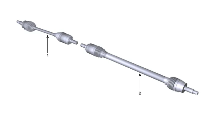
| 1. Front driveshaft (LH) |
2. Front driveshaft (RH) |
Repair procedures
| Removal |
| 1. |
Disconnect the (-) battery terminal. |
| 2. |
Remove the front wheel and tire. (Refer to Suspension System - "Wheel") |
| 3. |
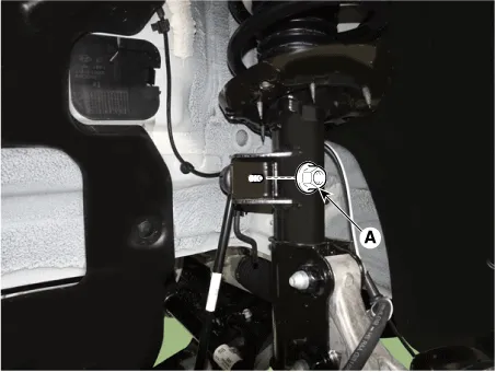
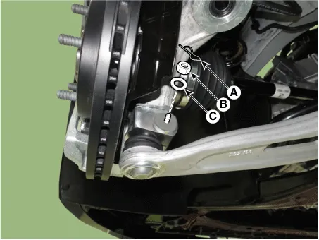
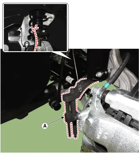
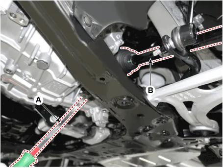
Separate the stabilizer bar link (A) from the strut assembly after loosening the nut.
|

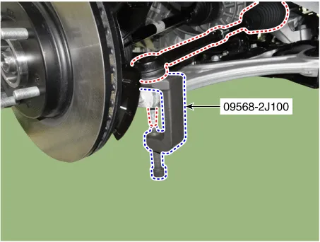
| 4. |
Disconnect the tie rod end ball joint from the knuckle by using the SST (09568-2J100).
|
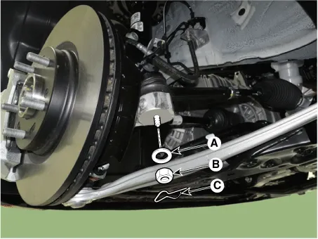
| 5. |
Loosen the lower arm mounting nut (A).
|
| 6. |
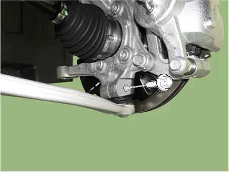
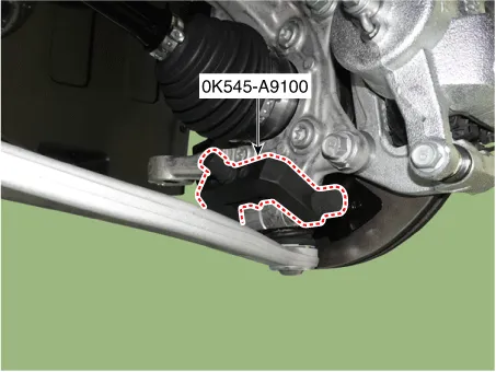
Disconnect lower arm ball joint from the knuckle by using the SST (0K545-A9100).
|
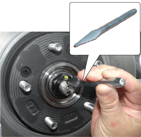
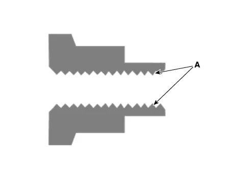
| 7. |
By hammering on a chisel, unlock the driveshaft lock hub nut caulking.
|
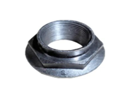
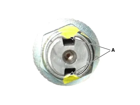
| 8. |
Remove the caulking nut (A) from the front axle.
|

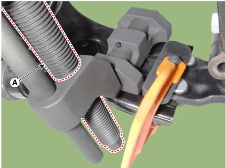
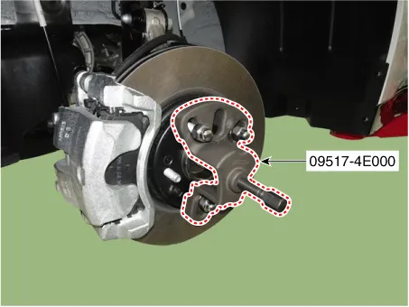
| 9. |
Disconnect the driveshaft from the axle hub by using the SST (09517-4E000).
|
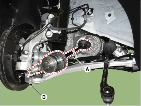
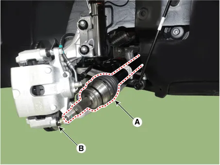
| 10. |
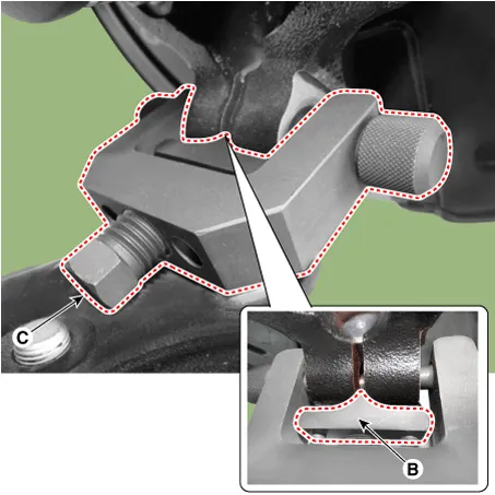
Separate the front driveshaft (A) from the knuckle assembly (B). [LH]
[RH]
|
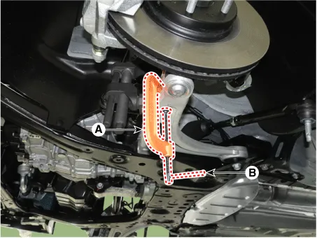
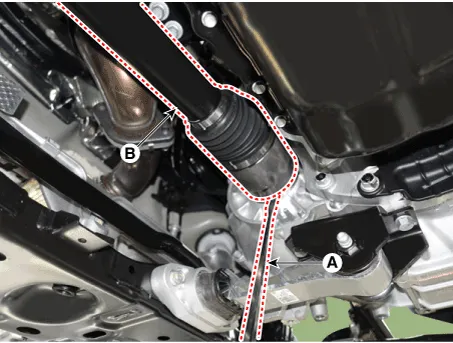
| 11. |
Remove the driveshaft (B) by using the pry bar (A). [LH]
[RH]
|
| Installation |
| 1. |
Install in the reverse order of removal. |
| 2. |
Check the front alignment. (Refer to Suspension System - "Alignment") |
| Inspection |
| 1. |
Check the driveshaft boots for damage and deterioration. |
| 2. |
Check the driveshaft spline for wear or damage. |
| 3. |
Check that there is no water or foreign material in the joint. |
| 4. |
Check the spider assembly for roller rotation, wear or corrosion. |
| 5. |
Check the groove inside the joint case for wear or corrosion. |
| 6. |
Check the dynamic damper for damage or cracks. |
Components and components location Components 1. Wheel side joint assembly 2. Wheel side circlip 3. Wheel side boot band 4.
Other information:
Kia Optima DL3 2019-2026 Service and Repair Manual: Overhead Console Lamp
Schematic diagrams Connector and Terminal Function [A Type] Connector A Pin E xcept Russia Region Russia only Function Function 1 Battery (+) Battery (+)
Kia Optima DL3 2019-2026 Service and Repair Manual: Photo Sensor
Description and operation Description The photo sensor is located at the center of the defrost nozzles. The photo sensor contains a photovoltaic (sensitive to sunlight) diode. The solar radiation received by its light receiving portion, generates an electromotive force in proportion to the amount of radiation received which is
Categories
- Manuals Home
- Kia Optima Owners Manual
- Kia Optima Service Manual
- Cooling System
- Identification Numbers
- Engine Control / Fuel System
- New on site
- Most important about car
