Kia Optima DL3: Front Suspension System / Front Lower Arm
Repair procedures
| Removal |
| 1. |
Disconnect the (-) battery terminal. |
| 2. |
Remove the front wheel and tire. (Refer to Suspension System - "Wheel") |
| 3. |
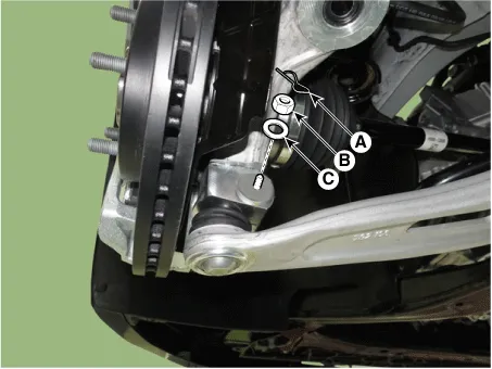
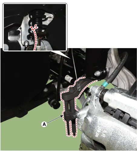
Loosen the lower arm mounting nut (A).
|

| 4. |
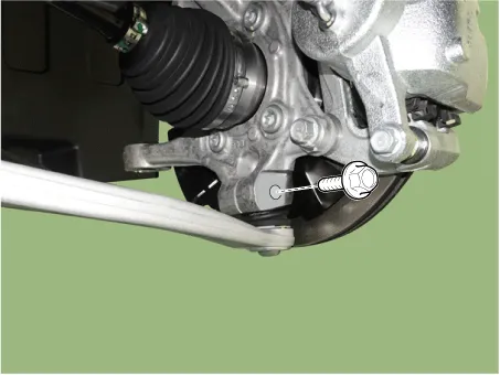
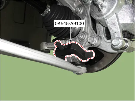
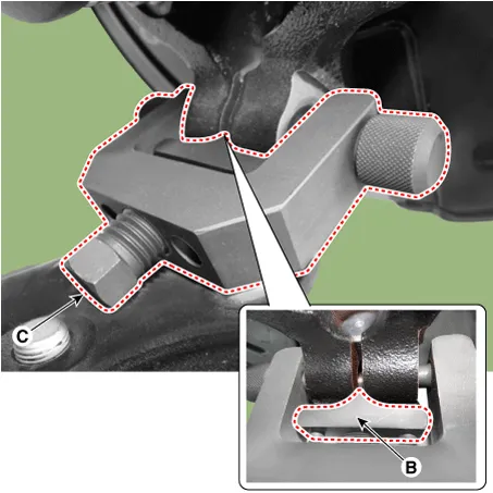
Disconnect lower arm ball joint from the knuckle by using the SST (0K545-A9100).
|


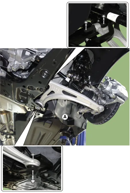
| 5. |
Loosen the bolts and nuts and remove the lower arm (A) from the sub frame.
|
| Installation |
| 1. |
Install in the reverse order of removal. |
| 2. |
Check the alignment. (Refer to Suspension System - "Alingment") |
| Inspection |
| 1. |
Check the bushing for wear and deterioration. |
| 2. |
Check the lower arm for bending or breakage. |
| 3. |
Check the lower arm for deformation. |
| 4. |
Check the all bolts and nuts. |
Components and components location Components 1. Strut assembly 2. Insulator dust cap 3. Insulator 4. Spring upper pad 5.
Repair procedures Removal 1. Disconnect the (-) battery terminal. 2. Remove the front wheel and tire.
Other information:
Kia Optima DL3 2019-2026 Service and Repair Manual: Photo Sensor
Description and operation Description The photo sensor is located at the center of the defrost nozzles. The photo sensor contains a photovoltaic (sensitive to sunlight) diode. The solar radiation received by its light receiving portion, generates an electromotive force in proportion to the amount of radiation received which is
Kia Optima DL3 2019-2026 Service and Repair Manual: Heater Core
Repair procedures Replacement 1. Disconnect the negative (-) battery terminal. 2. Remove the heater and blower assembly. (Refer to Heater - "Heater Unit") 3. Loosen the mounting screws and remove the heater core cover (A).
Categories
- Manuals Home
- Kia Optima Owners Manual
- Kia Optima Service Manual
- Floor Console Assembly
- Engine Control / Fuel System
- Identification Numbers
- New on site
- Most important about car
