Kia Optima DL3: Surround View Monitor (SVM) / Surrount View Monitor (SVM) Switch
Schematic diagrams
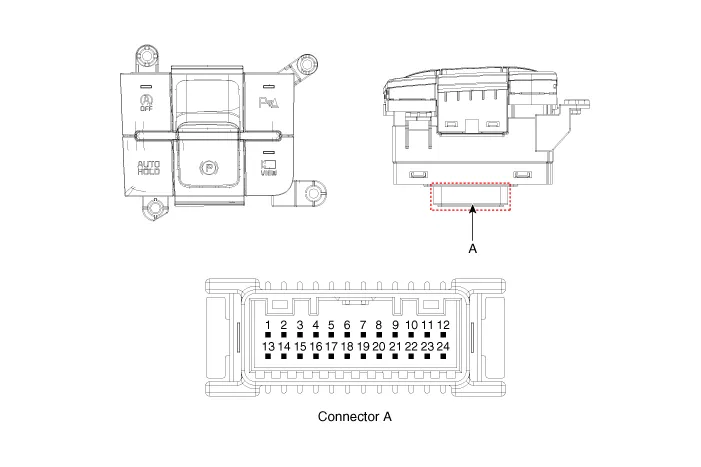
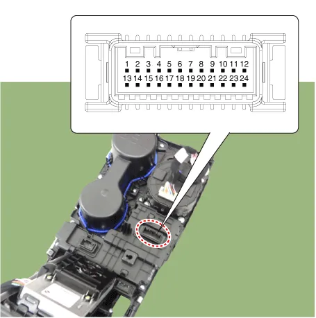
| Connector and Terminal Function |
|
Pin |
Function |
Pin |
Function |
|
1 |
PAS mode switch |
13 |
SVM mode indicator |
|
2 |
PAS mode indicator |
14 |
SVM mode switch |
|
3 |
- |
15 |
- |
|
4 |
Detent |
16 |
Ground |
|
5 |
EPB switch1 |
17 |
EPB switch2 |
|
6 |
EPB switch3 |
18 |
EPB switch4 |
|
7 |
- |
19 |
- |
|
8 |
- |
20 |
IGN1 |
|
9 |
Battery (+) |
21 |
illumination (+) |
|
10 |
- |
22 |
- |
|
11 |
ISG mode indicator |
23 |
illumination (-) |
|
12 |
ISG mode switch |
24 |
Auto hold mode |
Repair procedures
| Removal |
|

| 1. |
Disconnect the negative battery terminal. |
| 2. |
Remove the console upper cover. (Refer to Body - "Floor Console Assembly") |
| 3. |
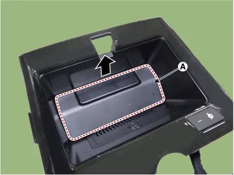
Remove the wireless power charger pad (A).
|
| 4. |
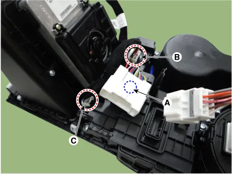
Disconnect the main connector fastener (A), consol switch connector (B) and wireless power charger indicator connector (C).
|
| 5. |
Remove the cup holder assembly (A) after loosening the mounting screws.
|
| 6. |
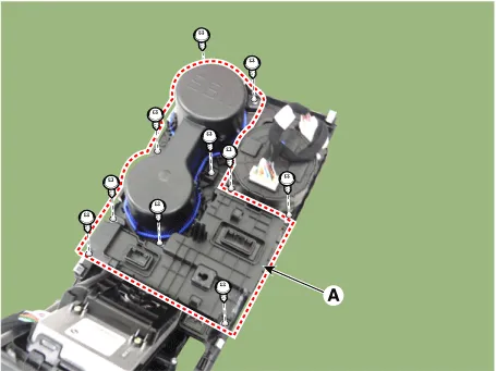
Remove the console switch (A) after loosening the mounting screws.
|
| Installation |
| 1. |
Install in the reverse order of removal. |
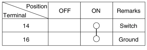
| Inspection |
| 1. |
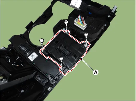
Remove the side crash pad switch. |
| 2. |
Operate the SVM switch, then check for continuity between terminals.
|
Schematic diagrams Connector and Terminal function Front View Camera Side View Camera Rear View Camera Repair procedures Removal In case of bad quality or poor focus, be sure to check the camera lens surface condition and foreign materials.
Specifications Specifications Item Specification Ultrasonic sensor Voltage rating DC 12 V Detecting range 30 - 120 cm (11.
Other information:
Kia Optima DL3 2019-2026 Service and Repair Manual: Keyless Entry And Burglar Alarm
Specifications Specification Item Specification Operating temperature 14 - 140°F (-10 - 60°C) RF Modulation FSK RF Frequency 433.
Kia Optima DL3 2019-2026 Service and Repair Manual: Air Conditioning System
General safety information and caution Instructions (R-134a) When Handling Refrigerant 1. R-134a liquid refrigerant is highly volatile. A drop on the skin of your hand could result in localized frostbite. When handling the refrigerant, be sure to wear gloves.
Categories
- Manuals Home
- Kia Optima Owners Manual
- Kia Optima Service Manual
- Suspension System
- Battery
- Identification Numbers
- New on site
- Most important about car
