Kia Optima DL3: Front Radar System / Front Radar Unit
Specifications
Item
|
Specification
|
Power supply
|
12 V
|
Operation voltage
|
9 - 16 V
|
Installation angle
|
Horizontal
|
0 ± 0.8°
|
Vertical
|
-1° ± 0.4°
|
Components and components location

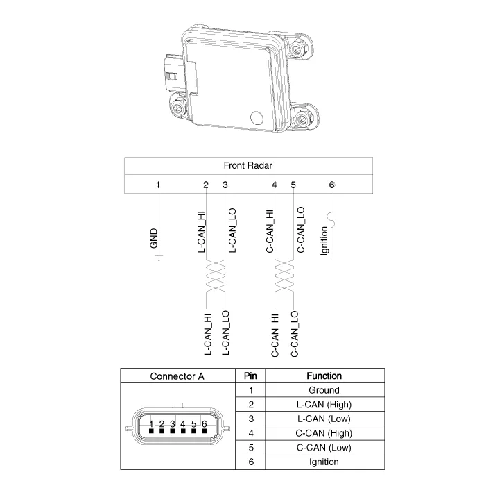
Schematic diagrams
Repair procedures
| Inspection procedures for front radar
system failure: |
| 1. |
Check the bumper appearance and accident history (visual appearance of
the vehicle, maintenance and bumper replacement history).
→ If the vehicle has been crashed, front radar unit mounting part is
highly likely to be twisted.
|
| 2. |
Check whether the radar cover of the bumper is dirty.
|
| 3. |
After starting engine, check the warning message on the cluster and DTC
code.
|
| 1. |
Disconnect the battery negative (-) terminal.
|
| 2. |
Remove the front bumper assembly.
(Refer to Body - "Front Bumper Assembly")
|
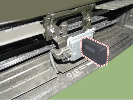
| 3. |
Disconnect the front radar connector (A).
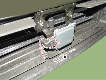
|
| 4. |
Remove the front radar (A) after loosening the nuts.
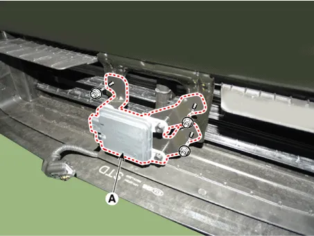
|
| • |
Put the vehicle on the level ground.
|
| • |
Take out heavy luggage from the vehicles’ seats or trunk.
|
| • |
Set all tires according to the specified pressure.
|
| • |
Check that the front surface of the front radar is clean.
|
|
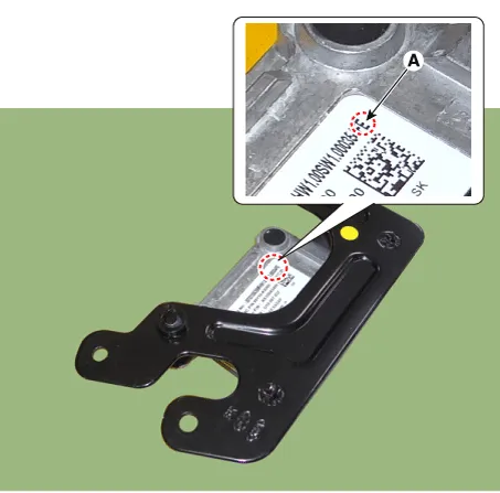
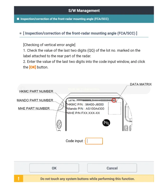
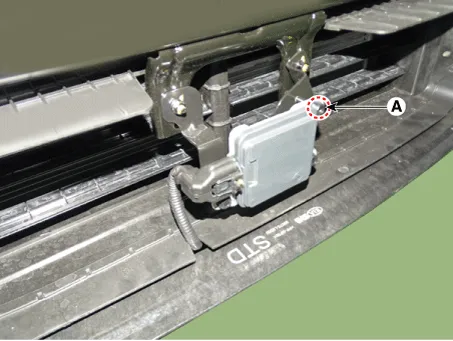
| 1. |
Check the last 2 digits of Lot. No (A) on label at rear side before installing
the front radar.
|
The meaning of Lot. No (A) is the vertical deviation angle of
front radar inner side.
|
|
| 2. |
Install the front radar (A) by tightening the nuts.
|
Tightening torque :
7.3 - 8.3 N·m (0.74 - 0.85 kgf·m, 5.4 - 6.1 lbf·ft)
|
|
| 3. |
Connect the front radar connector (A).
|
| 4. |
If the front radar was replaced with a new one, perform variant coding
procedure by using the KDS.
|
| 5. |
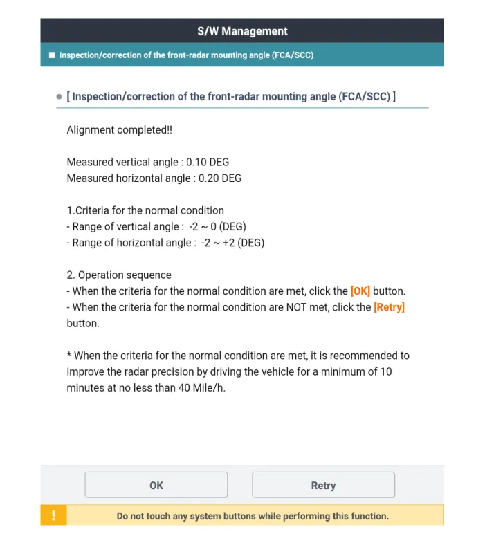
Check and align the front radar mounting angle.
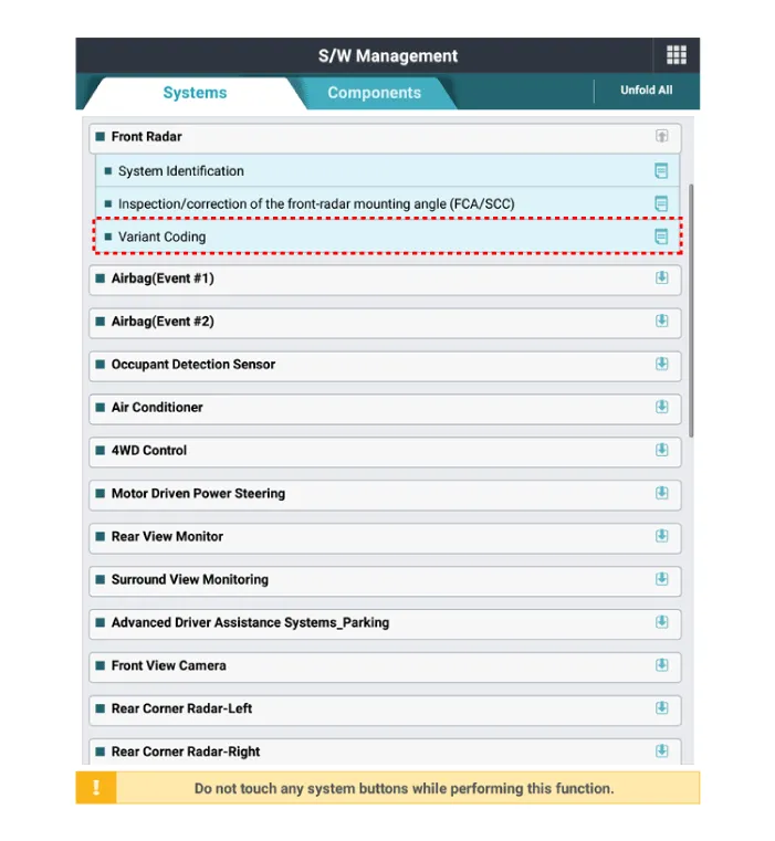
| (1) |
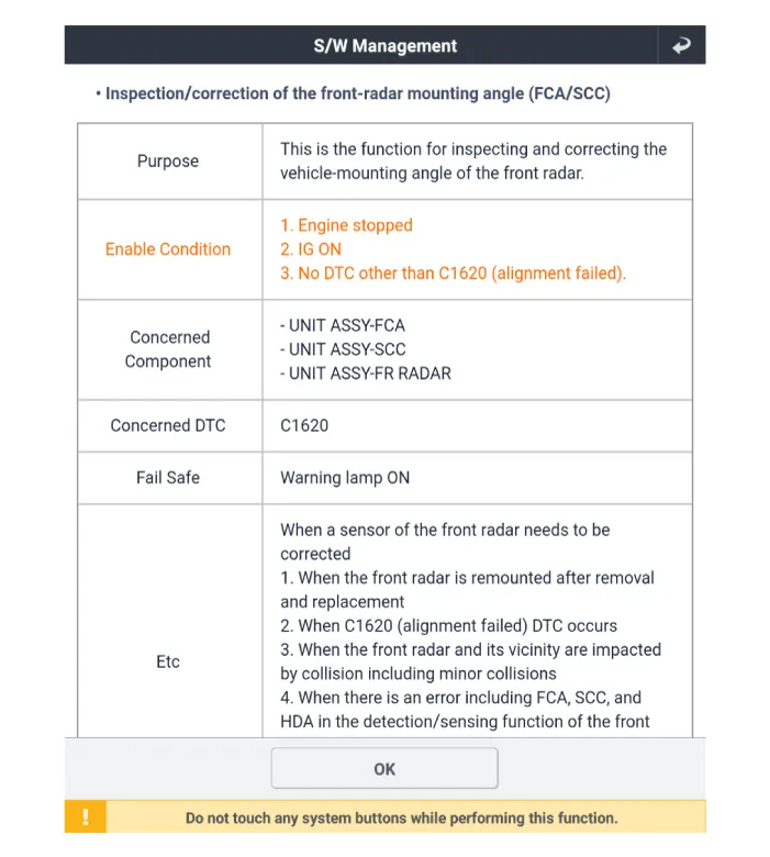
Perform the “inspection/correction of the front-radar mounting
angle” using the KDS.

|
| (2) |
Input the two digit value in the code input box, then press "OK"
|
| (3) |
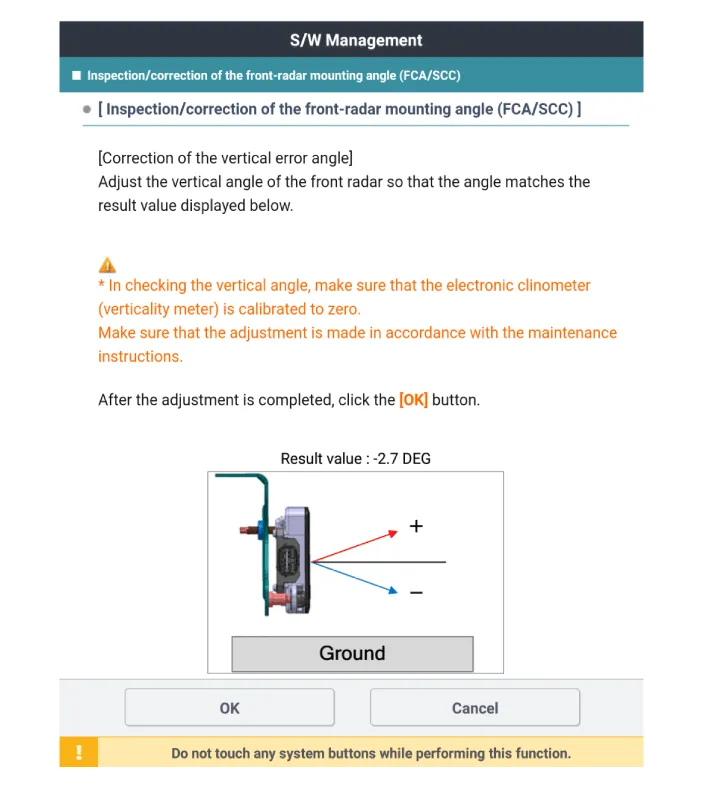
Check for any compensated vertical angle errors in KDS.
|
The final result value for the vertical angle should
be -1°.
|
|
| (4) |
Check the front radar vertical angle by using the vertical protractor
(tiltmeter).
|
• |
Make sure to perform zero setting before using
vertical protractor. (perform this procedure before
performing any adjustments)
|
|
• |
Be careful with +/- readings when finding true
vertical using vertical protractor.
|
|
|
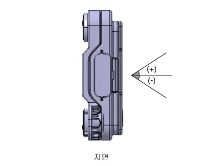
| (5) |
Adjust to "target vertical angle" by turning adjusting screw
(A) of front radar.
|
Vertical angle : -1 ± 0.4°
|
| –
|
turning clockwise : adjusting (+) angle
|
| –
|
turning counterclockwise : adjusting (-) angle
|
|
• |
Adjustment of the bracked can be applied using
manual pressure.
|
|
• |
Must recheck with vertical protractor if vertical
angle is right after adjusting.
|
|
Number of adjustment screw rotation
|
Correction angle
|
Clockwise
|
Counter clockwise
|
0.5
|
+ 0.5°
|
- 0.5°
|
1
|
+ 1.0°
|
- 1.0°
|
1.5
|
+ 1.5°
|
- 1.5°
|
2
|
+ 2.0°
|
- 2.0°
|
2.5
|
+ 2.5°
|
- 2.5°
|
3
|
+ 3.0°
|
- 3.0°
|
3.5
|
+ 3.5°
|
- 3.5°
|
4
|
+ 4.0°
|
- 4.0°
|
4.5
|
+ 4.5°
|
- 4.5°
|
5
|
+ 5.0°
|
- 5.0°
|
|
|
| 6. |
Install the front bumper assembly.
(Refer to Body - "Front Bumper Assembly")
|
| 7. |
Perform the front radar inspection/correction procedure by using the
SSTs.
(Refer to Front Radar Unit - "Adjustment")
|
Front radar installation
angle checking/adjustment overview
The front radar detects the object in front of the vehicle, and recognizes the
distance from the object,comparing speed, etc,. For these reasons the direction
of installation has to be llinear with vehicle. Therefore, performing angle inspection
and adjustment have to be done in case of the front radar repairs caused by accident
or failure and replacement of a new front radar.
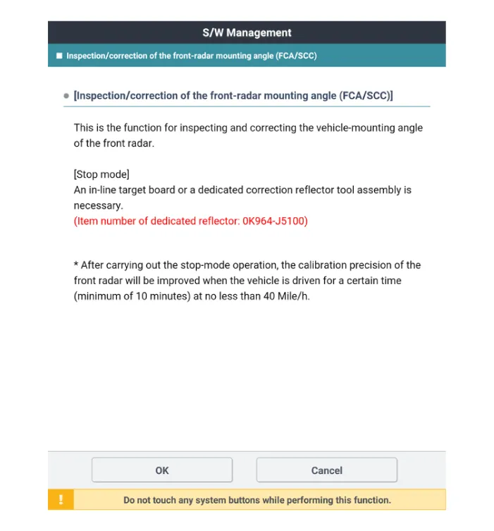
Accuracy of the front radar cannot be guaranteed if inspection and adjustment
have not been performed properly.
Perform adjustment procedure with exclusive adjustment reflector (SST) for stop
mode.
|
The front radar installation angle checking/adjustment are needed in
the following cases.
| • |
Front radar has been replaced
|
| • |
Front radar has been removed and reinstalled.
|
| • |
Calibration failure DTC is present
|
| • |
Front radar detecting and recognition function failure.
|
| – |
failed to detect vehicle in front while functioning
|
| – |
often detecting error of road side lane
|
| – |
often detecting error of object when no objects are present
|
|
How to check/adjust
front radar installation angle - stop mode
|
Preparation before the front radar alignment:
| • |
Put the vehicle on the level ground.
|
| • |
Take out heavy luggage from the vehicles’ seats or trunk.
|
| • |
Set all tires according to the specified pressure.
|
| • |
Check that the front surface of the front radar is clean.
|
|
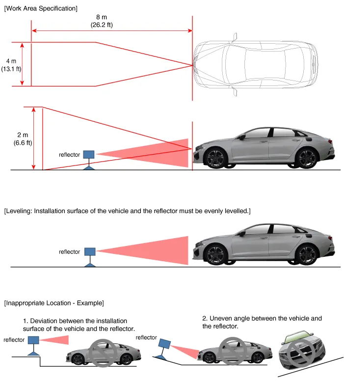
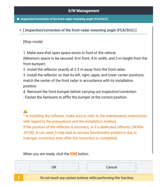
| • |
Perform in an area with minimum clearance of 8m (26.2 ft) front,
4m (13.1 ft) sides, and 2 m (6.6 ft) above the vehicle.
|
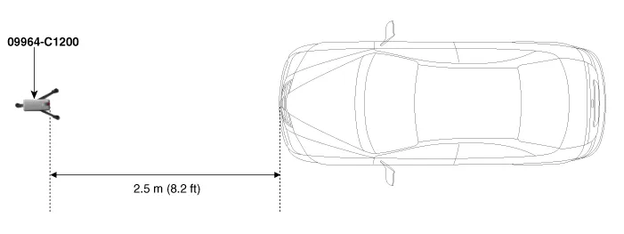
| • |
Install the reflector exactly 2.5 m (8.2 ft) away from the Front
Radar.
|
| • |
The reflector has to be installed at same place (height and angle)
as front radar center.
(If height and angle are different, then adjustment can not be
done correctly.)
|
| • |
Remove objects (metal plates, resins, etc.) that may cause electric
signal interference from the area where front radar alignment is
performed.
|
| • |
Make sure to use exclusive reflector (OK964-J5100)
|
| • |
Be sure that the vehicle is not moved and free from vibration
when performing front radar alignment
(getting in/out or opening/closing doors).
|
| • |
When performing front radar alignment, the ignition has to be
in the ON position (engine OFF).
|
|
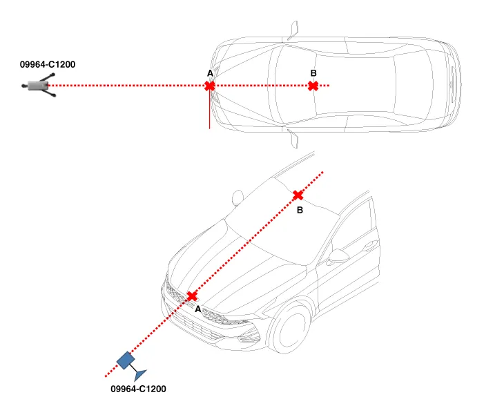
| 1. |
Park the vehicle in a flat ground.
|
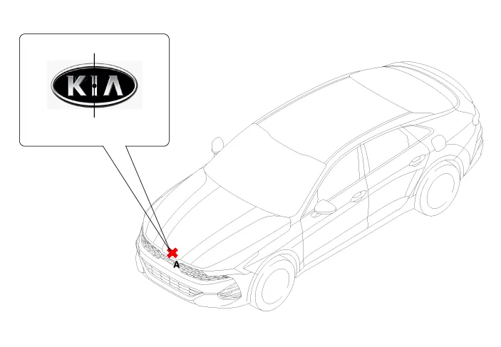
| 2. |
Mark the center point of emblem (A).
|
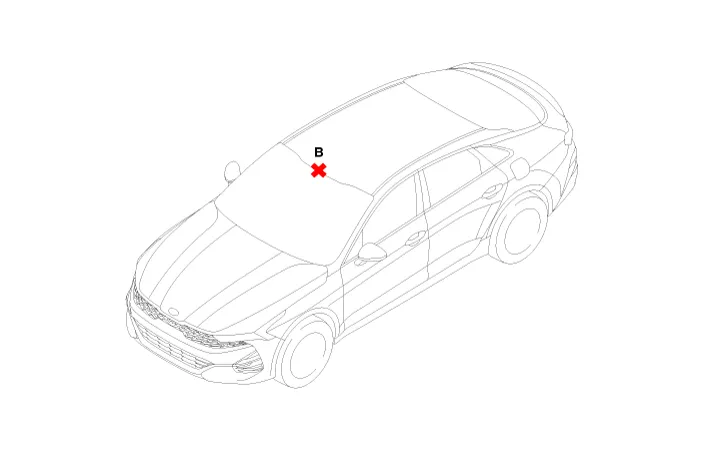
| 3. |
Mark the center point (B) after measuring the distance on top of the
windshield glass.
|
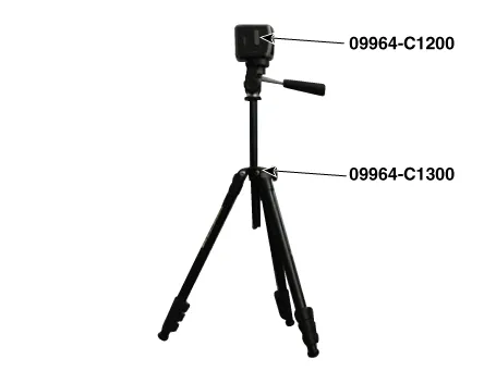
| 4. |
Install the laser (09964-C1200) to the tripod (09964-C1300).
|
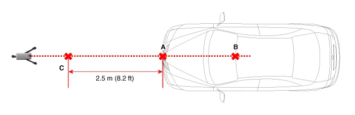
| 5. |
Place the laser (09964-C1200) at 2.5m (8.2 ft) to the front of the vehicle.
|
| 6. |
Match the vertical line of laser to (A) and (B) using the laser (09964-C1200).
|
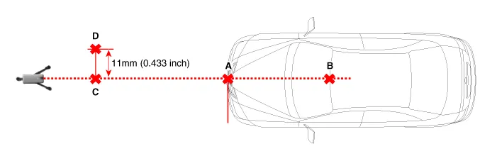
| 7. |
Mark location (C) at 2.5m (8.2 ft) from (A) in front of the vehicle.
|
| 8. |
Mark location (D) as shown below at 11mm (0.433 inch) away from (C) to
the left (passenger side) of the vehicle.
|
| 9. |
Remove the laser (09964-C1200) from the tripod (09964-C1300).
|
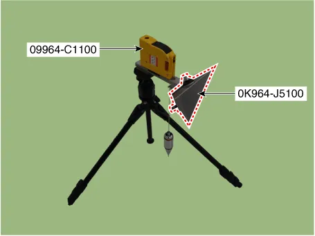
| 10. |
Mount the reflector (09964-C1100) onto the tripod (09964-C1300).

|
| 11. |
Mount the reflector adapter (0K964-J5100) to the reflector (09964-C1100).
|
| 12. |
Set the reflector horizontal using the leveler (A) which is built in
the tripod (09964-C1300).
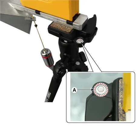
|
| 13. |
Align the vertical weight (A) of the reflector (09964-C1100) with the
point (D).
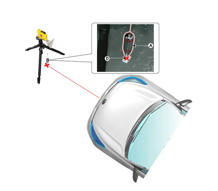
|
| 14. |
Set the height of the reflector adapter (0K964-J5100) to 333 mm (13.11
inch).

|
| 15. |
Remove the vertical weight from the reflector (09964-C1100).
| •
|
If the weight is not removed it can affect the adjustment.
|
|
|
| 16. |
Check again the front radar and the surface of front bumper for the following
items with the eyes.
| •
|
Make sure that there is no debris, or reflecting object
on the surface of the radar.
|
| •
|
Make sure that there is no debris, or reflecting object
on the radiator grill.
|
|
|
| 17. |
Inspect and adjust the front radar installation angle by following procedure
on KDS screen.
|
| 18. |
In case of front radar inspection/correction failure, check the inspection/correction
conditions.
|
Components and components location
Components Location
1. Smart Cruise Control (SCC)
switch
2. Front radar unit
Description and operation
Description
System Function
•
Forward Collision-avoidance Assist (FCA) : Detects the risk factors on
the road and warn the driver and activate the emergency brake to prevent
collision or reduce collision speed.
Components and components location
Components
1. Left remote control switch
(Audio + Bluetooth + Voice)
2. Right remote control switch
(Trip + SCC + LFA)
Schematic diagrams
Circuit Diagram
Repair procedures
Removal
1.
Other information:
Components and components location
Component Location
1. Low beam
2. High beam
3. Daytime Running Light / Position lamp
4. Low assist beam
5. Turn signal lamp
Schematic diagrams
Connector and Terminal Function
Connector
Terminal Function
Components and components location
Components Location
1. Condenser
Repair procedures
Inspection
1.
Check the condenser fins for clogging and damage. If clogged, clean them
with water, and blow them with compressed air.


