Kia Optima DL3: SRSCM / SRS Control Module (SRSCM)
Description and operation
| Description |
The primary purpose of the SRSCM (Supplemental Restraints System Control Module) is to discriminate between an event that warrants restraint system deployment and an event that does not. The SRSCM must decide whether to deploy the restraint system or not. After determining that pretensioners and/or airbag deployment is required, the SRSCM must supply sufficient power to the pretensioners and airbag igniters to initiate deployment.
The SRSCM determines that an impact may require deployment of the pretensioners and airbags from data obtained from impact sensors and other components in conjunction with a safing function.
The SRSCM will not be ready to detect a crash or to activate the restraint system devices until the signals in the SRSCM circuitry is stabilized.
It is possible that the SRSCM could activate the safety restraint devices in approximately 2 seconds but is guaranteed to fully function after prove-out is completed.
The SRSCM must perform a diagnostic routine and light a system readiness indicator when the ignition switch is in the ON position. The system must perform a continuous diagnostic routine and provide fault notice through a warning lamp indicator in the event of fault detection. A serial diagnostic communication interface will be used to facilitate servicing of the restraint control system.
Components and components location
| Components Location |
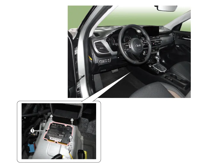
| 1. Supplemental Restraint System
Control Module (SRSCM) |
Schematic diagrams
| Supplemental Restraint System Control Module (SRSCM) |

|
No |
Connector A |
Connector B |
|
1 |
Driver airbag #1 (High) |
- |
|
2 |
Driver airbag #2 (Low) |
- |
|
3 |
Passenger airbag #2 (Low) |
- |
|
4 |
Passenger airbag #2 (High) |
Driver rear side airbag ( Low) |
|
5 |
- |
Driver rear side airbag (High) |
|
6 |
- |
Passenger rear side airbag ( High) |
|
7 |
- |
Passenger rear side airbag ( Low) |
|
8 |
- |
- |
|
9 |
- |
- |
|
10 |
B+ |
- |
|
11 |
Crash output |
- |
|
12 |
Passenger airbag #1 (Low) |
- |
|
13 |
Passenger airbag #1 (High) |
- |
|
14 |
Driver knee airbag (High) |
- |
|
15 |
Driver knee airbag (Low) |
Passenger seat belt buckle sensor (High) |
|
16 |
Passenger airbag OFF Lamp (Telltale) |
Driver seat belt buckle sensor (High) |
|
17 |
- |
Passenger curtain airbag (Low) |
|
18 |
- |
Passenger curtain airbag (High) |
|
19 |
Driver airbag #1 (High) |
Driver curtain airbag (High) |
|
20 |
Driver airbag #1 (Low) |
Driver curtain airbag (Low) |
|
21 |
- |
Passenger side airbag (Low) |
|
22 |
- |
Passenger side airbag (High) |
|
23 |
- |
Driver side airbag (High) |
|
24 |
- |
Driver side airbag (Low) |
|
25 |
- |
- |
|
26 |
C-CAN (Low) |
- |
|
27 |
C-CAN (High) |
Driver seat belt pretensioner (Low) |
|
28 |
IGN 1 |
Driver seat belt pretensioner (High) |
|
29 |
Driver front impact sensor (High) |
- |
|
30 |
Driver front impact sensor (Low) |
- |
|
31 |
Passenger front impact sensor (Low) |
- |
|
32 |
Passenger front impact sensor (High) |
Passenger seat belt pretensioner (High) |
|
33 |
- |
Passenger seat belt pretensioner (Low) |
|
34 |
- |
- |
|
35 |
P-CAN (Low) |
- |
|
36 |
P-CAN (High)) |
- |
|
37 |
|
- |
|
38 |
- |
|
|
39 |
- |
|
|
40 |
Ground |
|
|
41 |
- |
|
|
42 |
- |
|
|
43 |
Driver pressure side impact sensor (High) |
|
|
44 |
Driver pressure side impact sensor (Low) |
|
|
45 |
Passenger pressure side impact sensor (Low) |
|
|
46 |
Passenger pressure side impact sensor (High) |
|
|
47 |
Driver gravity side impact sensor (High) |
|
|
48 |
Driver gravity side impact sensor (Low) |
|
|
49 |
Passenger gravity side impact sensor (Low) |
|
|
50 |
Passenger gravity side impact sensor (High) |
|
|
51 |
- |
|
|
52 |
- |
Repair procedures
| Removal |
| 1. |
Disconnect the battery negative terminal.
|

| 2. |
Remove the floor console assembly. (Refer to Body - "Floor Console Assembly") |
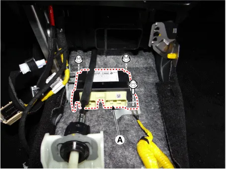
| 3. |
Disconnect the SRSCM connectors (A).
|

| 4. |
Remove the SRSCM (A) by loosening the bolt and nuts.
|
| Installation |
| 1. |
Install in the reverse of the removal. |
| 2. |
After installing the SRSCM, confirm proper system operation: Switch ON the ignition. The SRS indicator light should turn on for about six seconds and then off. |
| Variant coding |
After replacing the SRSCM with a new one, the "Variant Coding" procedure MUST be performed.
|

Variant coding Procedure
| ■ On-Line on KDS |
| 1. |
Switch "OFF" ignition, and connect KDS. |
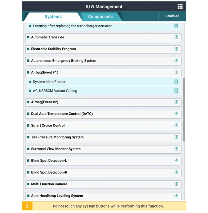
| 2. |
With ignition "ON" & Engine "OFF", select vehicle name and airbag system. |
| 3. |
Select Variant coding mode.
|
| 4. |
Enter the VIN code. |
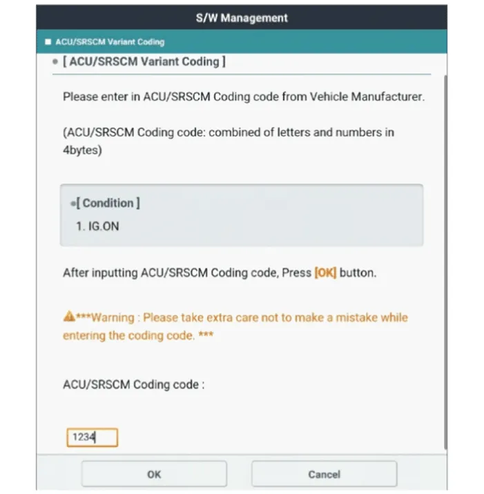
| ■ Off-Line on KDS |
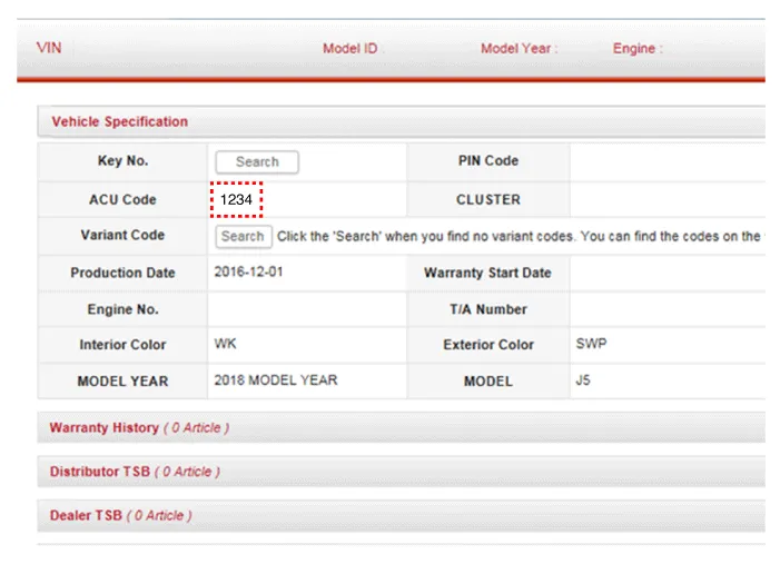
| 1. |
Confirm the ACU variant coding code from the KDS server after inputting the VIN to the KDS sever.
|
| 2. |
Switch "OFF" ignition, and connect KDS. |
| 3. |
With ignition "ON" & Engine "OFF", select vehicle name and airbag system. |
| 4. |
Select Variant coding mode. |
| 5. |
Input the ACU coding code.
|
Components and components location Components 1. Supplemental Restraint System Control Module (SRSCM) 2. Gravity Side Impact Sensor (G-SIS) 3.
Description and operation Description The front impact sensor (FIS) is installed in the Front End Module (FEM). They are remote sensors that detect acceleration due to a collision at its mounting location.
Other information:
Kia Optima DL3 2019-2026 Service and Repair Manual: Ventilated and Heated Seat Switch
Schematic diagrams Connector and Terminal Function [Front Seat] [Ventilation+Heater Type / Non-Heater Type] Pin Function Pin Function Ventilation+Heater Type Non-Heater Type Ventilation+Heater Type Non-Heater Type
Kia Optima DL3 2019-2026 Service and Repair Manual: In-car Sensor
Description and operation Description The In-car air temperature sensor is built in the heater & A/C control unit. The sensor contains a thermistor which measures the temperature of the inside. The signal decided by the resistance value which changes in accordance with perceived inside temperature, is delivered to heater co
Categories
- Manuals Home
- Kia Optima Owners Manual
- Kia Optima Service Manual
- Cooling System
- Motor Driven Power Steering
- Brake System
- New on site
- Most important about car
