Kia Optima DL3: Fuel Delivery System / Fuel Line
Components and components location
| Component |
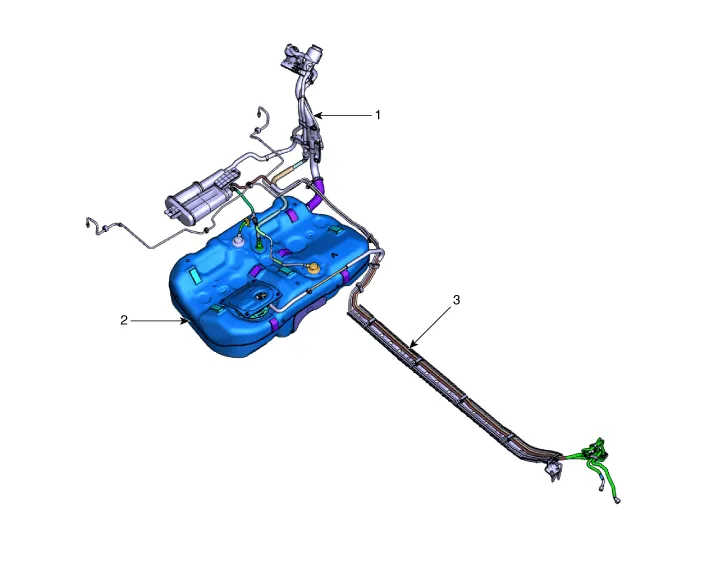
| 1. Filler-Neck Assembly 2. Fuel Tank Complete |
3. Fuel Line |
Repair procedures
| Removal |
| 1. |
Release the residual pressure in fuel line. (Refer to Fuel Delivery System - "Release Residual Pressure in Fuel Line")
|

| 2. |
Disconnect the negative battery terminal. |
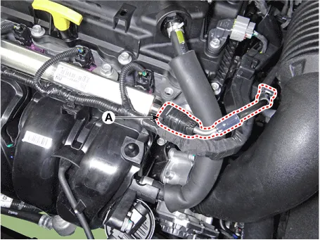
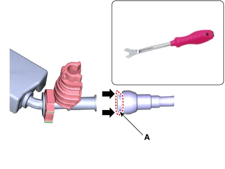
| 3. |
Separate the fuel feed tube quick-connector (A).
|

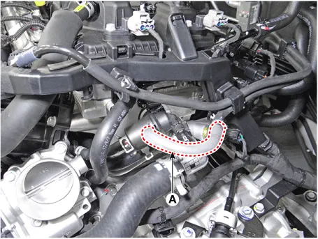
| 4. |
Separate the vapor hose (A).
|
| 5. |
Remove the fuel tank. (Refer to Fuel Delivery System - "Fuel Tank") |
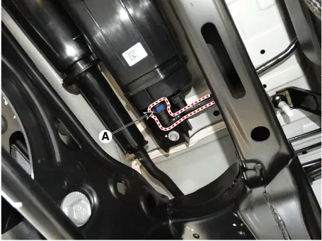
| 6. |
Disconnect the vapor quick-connector (A) from the canister.
|
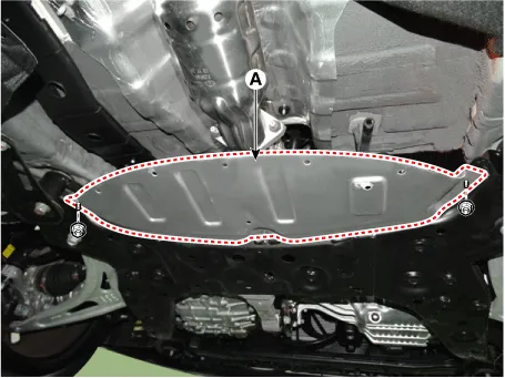
| 7. |
Remove the cover (A) after loosening the mounting nuts.
|
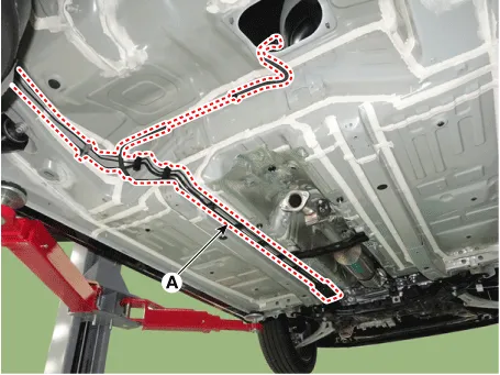
| 8. |
Remove the fuel line (A) from the vehicle after removing the fixing clips.
|

| Installation |
| 1. |
Install in the reverse order of removal. |
Components and components location Component 1. Plate Assembly 2. Clip 3. O-ring 4. Fuel Reservoir Cup 5.
Components and components location Components 1. Filler-Neck Assembly 2. Canister 3. Fuel Tank Complete Repair procedures Removal 1.
Other information:
Kia Optima DL3 2019-2026 Service and Repair Manual: Overhead Console Lamp
Schematic diagrams Connector and Terminal Function [A Type] Connector A Pin E xcept Russia Region Russia only Function Function 1 Battery (+) Battery (+)
Kia Optima DL3 2019-2026 Service and Repair Manual: Power Door Lock Module
Repair procedures Inspection When prying with a flat-tip screwdriver or use a prying trim tool, wrap it with protective tape, and apply protective tape around the related parts, to prevent damage.
Categories
- Manuals Home
- Kia Optima Owners Manual
- Kia Optima Service Manual
- Front Axle Assembly
- Identification Numbers
- Battery
- New on site
- Most important about car
