Kia Optima DL3: Cylinder Block / Crankshaft
Components and components location
| Components |
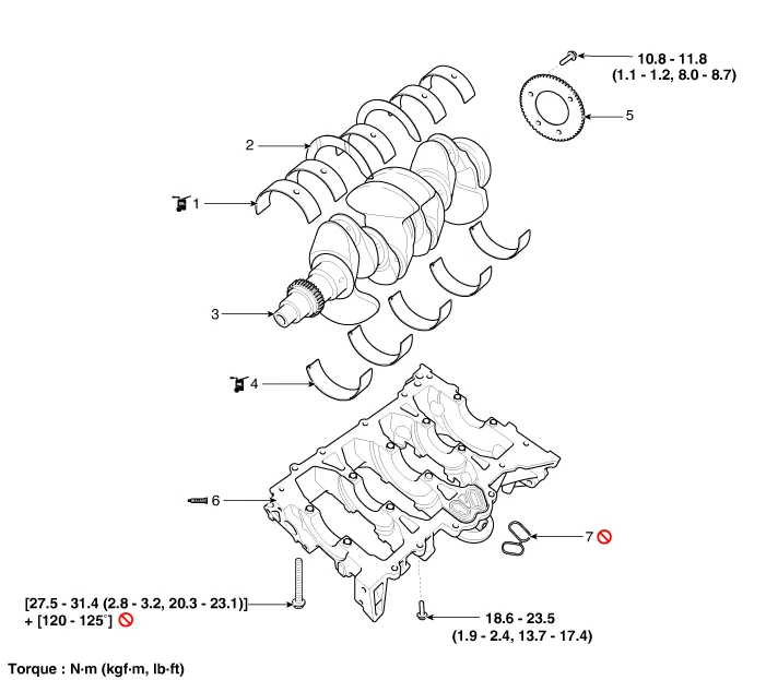
| 1. Crankshaft upper bearing
2. Crankshaft thrust bearing 3. Crankshaft 4. Crankshaft lower bearing |
5. Crankshaft position sensor
(CKPS) wheel 6. Lower crankcase 7. Gasket |
Repair procedures
| Disassembly |
|

|

| 1. |
Remove the engine assembly from the vehicle. (Refer to Engine and Transaxle Assembly - “Engine and Transaxle Assembly”) |
| 2. |
Remove the transaxle assembly from the engine assembly. (Refer to Automatic Transaxle System - "Automatic Transaxle") |
| 3. |
Remove the drive plate. (Refer to Cylinder Block - "Drive Plate") |
| 4. |
Remove the rear oil seal. (Refer to Cylinder Block - “Rear Oil Seal”) |
| 5. |
Install the engine to engine stand for disassembly. |
| 6. |
Remove the timing chain. (Refer to Timing System - “Timing Chain”) |
| 7. |
Remove the water pump assembly. (Refer to Cooling System - “Water Pump”) |
| 8. |
Remove the water inlet fitting and the thermostat assembly. (Refer to Cooling System - “Thermostat“) |
| 9. |
Remove the intake manifold. (Refer to Intake and Exhaust System - "Intake Manifold") |
| 10. |
Remove the A/C compressor. (Refer to Heating, Ventilation Air conditioning -"Compressor") |
| 11. |
Remove the exhaust manifold. (Refer to Intake and Exhaust System - "Exhaust Manifold") |
| 12. |
Remove the cylinder head assembly. (Refer to Cylinder Head Assembly - "Cylinder Head") |
| 13. |
Remove the oil filter. (Refer to Lubrication System - “Engine Oil”) |
| 14. |
Remove the oil screen. (Refer to Lubrication System - “Oil Pan”) |
| 15. |
Remove the piston and connecting rod assemblies. (Refer to Cylinder Block - "Piston and Connecting Rod") |
| 16. |
Check the crankshaft bearing oil clearance. |
| 17. |
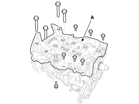
Remove the lower crankcase (A).
|
| 18. |
Check the crankshaft end play. |
| 19. |
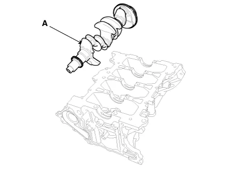
Lift the crankshaft (A) out of the engine, being careful not to damage journals.
|
| Inspection |
| 1. |
Check the crankshaft bearing oil clearance.
|
|||||||||||||||||||||||||||||||||||||||||||||||||||||||||||||||||||||||||||||||||||||||||||||||||||||||||||
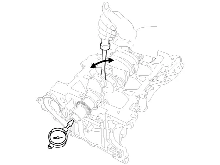
| 2. |
Check crankshaft end play. Using a dial indicator, measure the thrust clearance while prying the crankshaft back and forth with a screwdriver. If the end play is greater than maximum, replace the center bearing.
|
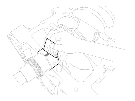
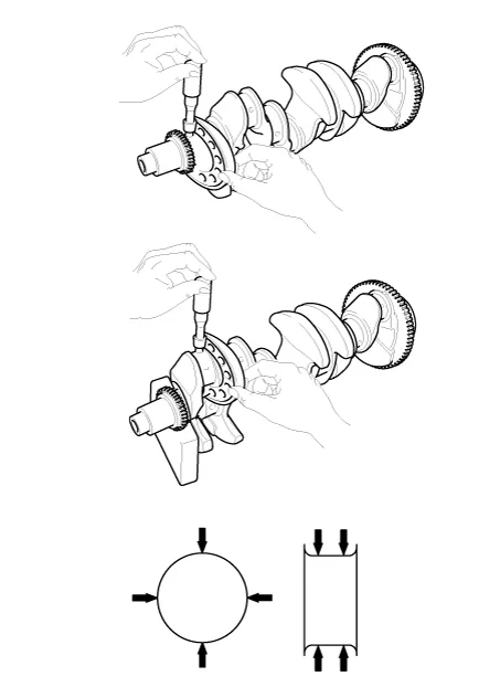
| 3. |
Inspect main journals and crank pins. Using a micrometer, measure the diameter of each main journal and crank pin.
|
| Reassembly |
|
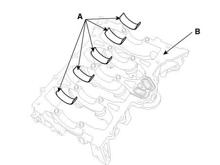
| 1. |
Install the crankshaft main bearings.
|
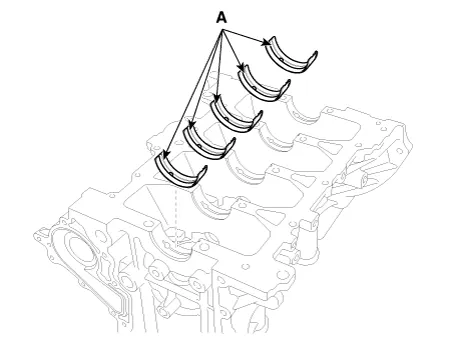
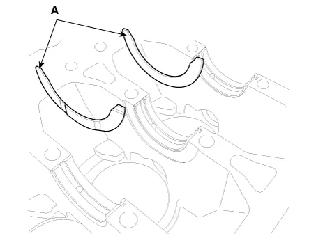
| 2. |
Install the thrust bearings. Install the 2 thrust bearings (A) on both sides of the No.3 journal of the cylinder block with the oil groove facing out.
|
| 3. |
Place the crankshaft (A) on the cylinder block.
|
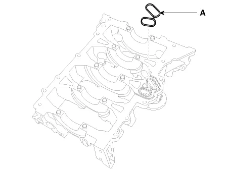
| 4. |
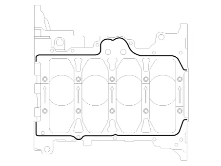
Apply liquid sealant on the top surface of the lower crankcase.
|
| 5. |
Place the lower crankcase on the cylinder block. |
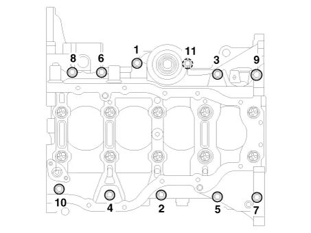
| 6. |
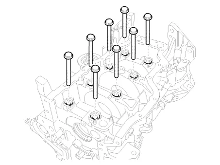
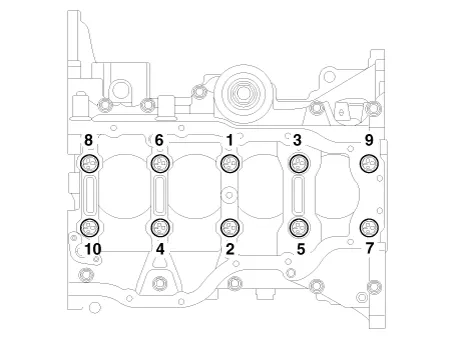
Install the main bearing cap bolts.
Using SST (09221-4A000), install and tighten the 10 main bearing cap bolts, in several passes, in the sequence as shown.
|
| 7. |
Install the lower crankcase bolts, in several passes, in sequence as shown.
Check that the crankshaft turns smoothly. |
| 8. |
Check the crankshaft end play. |
| 9. |
Assemble the other parts in the reverse order of disassembly. |
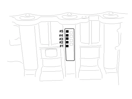
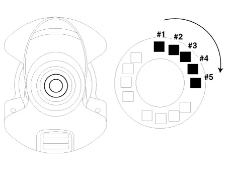
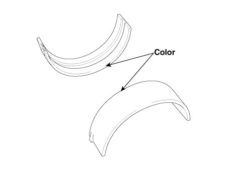
In case the crankshaft is replaced with a new one, select the proper connecting rod bearing according to the pin journal mark on the crankshaft.
|
Components and components location Components 1. Piston ring 2. Snap ring 3. Piston pin 4. Piston 5. Connecting rod 6.
Repair procedures Disassembly • Use fender covers to avoid damaging painted surfaces.
Other information:
Kia Optima DL3 2019-2026 Service and Repair Manual: Power Window Switch
Schematic diagrams Connector and Terminal Function Power Window Main Switch Pin Function 1 B-CAN (Low) 2 B-CAN (High) 3 Ground (Assist safety) 4 Assist safety 5
Kia Optima DL3 2019-2026 Service and Repair Manual: Heater & A/C Control Unit (DATC)
Components and components location Components Connector Pin NO Funtion Pin NO Funtion 1 Ground 9 Ground 2 ILL- 10 - 3 - 11
Categories
- Manuals Home
- Kia Optima Owners Manual
- Kia Optima Service Manual
- Rear Brake Disc
- Timing Chain
- Suspension System
- New on site
- Most important about car
