Kia Optima DL3: Cylinder Block / Cylinder Block
Repair procedures
| Disassembly |
|

|

| 1. |
Remove the engine assembly from the vehicle. (Refer to Engine and Transaxle Assembly - “Engine and Transaxle Assembly”) |
| 2. |
Remove the transaxle assembly from the engine assembly. (Refer to Automatic Transaxle System - "Automatic Transaxle") |
| 3. |
Remove the drive plate. (Refer to Cylinder Block - "Drive Plate") |
| 4. |
Remove the rear oil seal. (Refer to Cylinder Block - “Rear Oil Seal”) |
| 5. |
Install the engine to engine stand for disassembly. |
| 6. |
Remove the timing chain. (Refer to Timing System - “Timing Chain”) |
| 7. |
Remove the water pump assembly. (Refer to Cooling System - “Water Pump”) |
| 8. |
Remove the water inlet fitting and the thermostat assembly. (Refer to Cooling System - “Thermostat“) |
| 9. |
Remove the intake manifold. (Refer to Intake and Exhaust System - "Intake Manifold") |
| 10. |
Remove the A/C compressor. (Refer to Heating, Ventilation Air conditioning -"Compressor") |
| 11. |
Remove the exhaust manifold. (Refer to Intake and Exhaust System - "Exhaust Manifold") |
| 12. |
Remove the cylinder head assembly. (Refer to Cylinder Head Assembly - "Cylinder Head") |
| 13. |
Remove the oil filter. (Refer to Lubrication System - “Engine Oil”) |
| 14. |
Remove the oil screen. (Refer to Lubrication System - “Oil Pan”) |
| 15. |
Remove the piston and connecting rod assemblies. (Refer to Cylinder Block - "Piston and Connecting Rod") |
| 16. |
Remove the crankshaft. (Refer to Cylinder Block - "Crankshaft") |
| 17. |
Remove the knock sensor. (Refer to Engine Control/Fuel System - "Knock Sensor (KS)") |
| 18. |
Remove the crankshaft position sensor (CKPS). (Refer to Engine Control/Fuel System - "Crankshaft Position Sensor (CKPS)") |
| 19. |
Remove the oil pressure switch. (Refer to Lubrication System - "Oil Pressure Switch") |
| Inspection |
| 1. |
Remove gasket material. Using a gasket scraper, remove all the gasket material from the top surface of the cylinder block. |
| 2. |
Clean cylinder block Using a soft brush and solvent, thoroughly clean the cylinder block. |
| 3. |
Inspect top surface of cylinder block for flatness. Using a precision straight edge and feeler gauge, measure the surface contacting the cylinder head gasket for warpage.
|
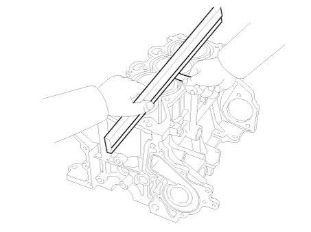
| 4. |
Inspect the cylinder bore Visually check the cylinder for vertical scratches. If deep scratches are present, replace the cylinder block. |
| 5. |
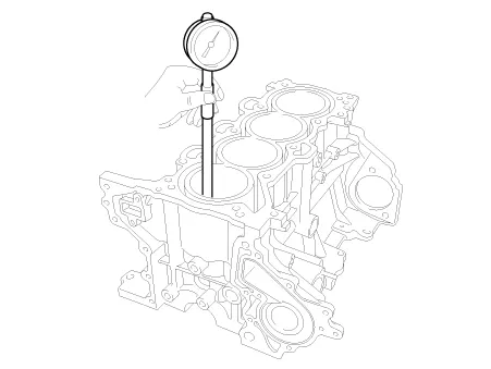
Inspect the cylinder bore diameter. Using a cylinder bore gauge, measure the cylinder bore diameter at position in the thrust and axial direction.
|
| Reassembly |
| 1. |
Assemble the other parts in the reverse order of disassembly. |
In case the cylinder block is replaced with a new one, select the proper crankshaft main bearing and the piston according to the crankshaft journal bore mark and the cylinder bore mark on the cylinder block.
|
Components and components location Components 1. Crankshaft upper bearing 2. Crankshaft thrust bearing 3. Crankshaft 4.
Components and components location Components 1. Camshaft bearing cap 2. Camshaft front bearing cap 3. Exhaust camshaft 4.
Other information:
Kia Optima DL3 2019-2026 Service and Repair Manual: Lumbar Support System
Repair procedures Inspection 1. Remove the front seat back. (Refer to Body - "Front Seat Back Cover") 2. Disconnect the connector (A). 3. When the battery power is supplied to the motor connector, check the motor for smooth operation.
Kia Optima DL3 2019-2026 Service and Repair Manual: Evaporator Core
Repair procedures Replacement 1. Disconnect the negative (-) battery terminal. 2. Remove the heater and blower assembly. (Refer to Heater - "Heater Unit") 3. Loosen the mounting screws, lock pin and remove the evaporator core cover (A).
Categories
- Manuals Home
- Kia Optima Owners Manual
- Kia Optima Service Manual
- Battery
- Heating, Ventilation and Air Conditioning
- Automatic Transaxle System
- New on site
- Most important about car
