
Kia Optima DL3: Heater / Heater Unit
Components and components location
| Component Location |
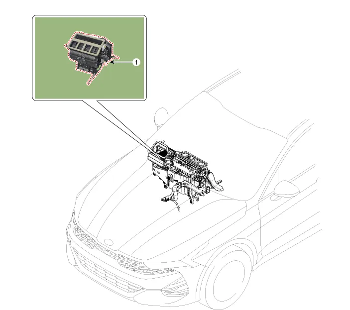
| 1. Heater unit assembly |
| Compoents |
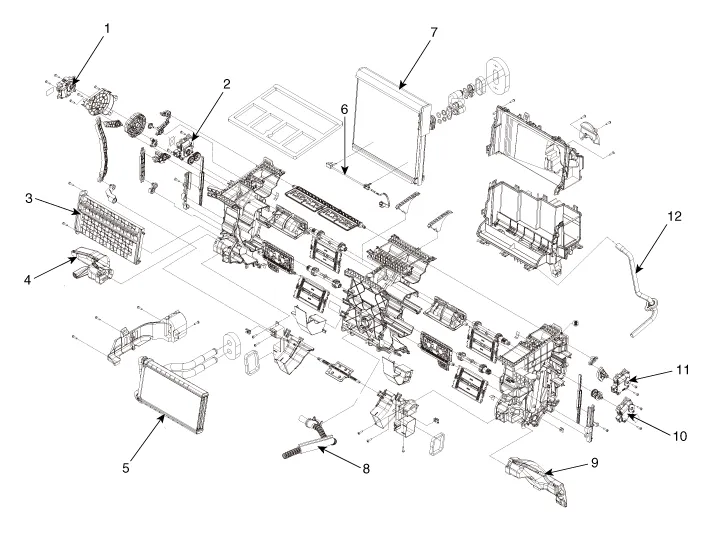
| 1. Mode control actuator 2. Temperature control actuator [LH] 3. PTC Heater dummy 4. Shower duct [LH] 5. Heater core assembly 6. Evaporator temperature sensor |
7. Evaporator core 8. Inhale hose 9. Shower duct [RH] 10. Temperature control actuator [RH] 11. Auto defogging actuator 12. Drain hose |
Repair procedures
| Replacement |
|

| 1. |
Disconnect the negative (-) battery terminal. |
| 2. |
Recover the refrigerant with a recovery/recycling/charging station. |
| 3. |
When the engine is cool, drain the engine coolant from the radiator. G 2.0 NU MPI (Refer to Engine Mechanical System - "Coolant") G 2.5 GDI THETA II (Refer to Engine Mechanical System - "Coolant") |
| 4. |
Remove the cowl top cover. (Refer to Body - "Cowl Top Cover") |
| 5. |
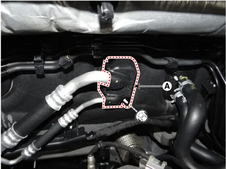
Loosen the mounting nut and remove the expension valve cover (A).
|
| 6. |
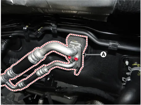
Loosen the mounting bolts and separate the expension valve (A) from the evaporator core.
|

| 7. |
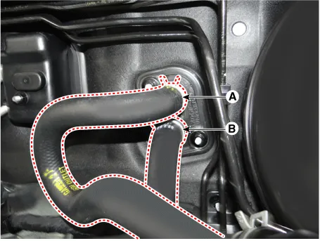
Separate the heater hose (A) and (B).
|
| 8. |
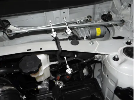
Loosen the cowl cross bar mounting bolts.
|
| 9. |
Remove the front seat assembly. (Refer to Body - "Front Seat Assembly") |
| 10. |
Remove the floor console assembly. (Refer to Body - "Floor Console Assembly") |
| 11. |
Remove the crash pad center panel. (Refer to Body - "Crash Pad Ceter Panel") |
| 12. |
Remove the front pillar trim. (Refer to Body - "Front Pillar Trim") |
| 13. |
Remove the cowl side trim. (Refer to Body - "Cowl Side Trim") |
| 14. |
Remove the steering column shroud lower panel. (Refer to Body - "Steering Column Shroud Panel") |
| 15. |
Remove the steering wheel. (Refer to Steering System - "Steering Wheel") |
| 16. |
Remove the multifunction switch. (Refer to Body Electrical System - "Multifunction Switch") |
| 17. |
Lower the steering column after loosening the mounting bolts. (Refer to Steering System - "Steering Column and Shaft") |
| 18. |
Remove the accelerator pedal. (Refer to Engine Control/Fuel System - "Accelerator Pedal") |
| 19. |
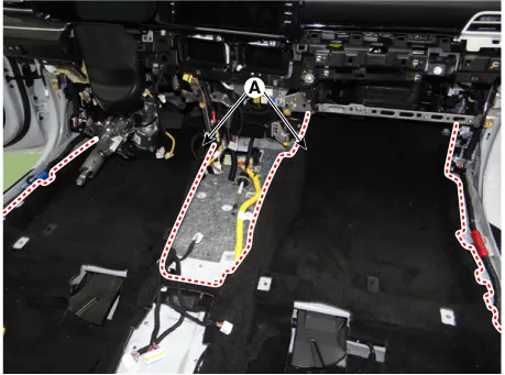
Separate the floor carpet (A) to obtain space for removing the rear heating duct.
|
| 20. |
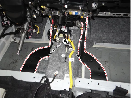
Remove the rear heating duct (A).
|
| 21. |
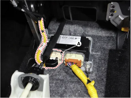
Separate the airbag control module (SRSCM) connector (A).
|
| 22. |
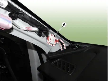
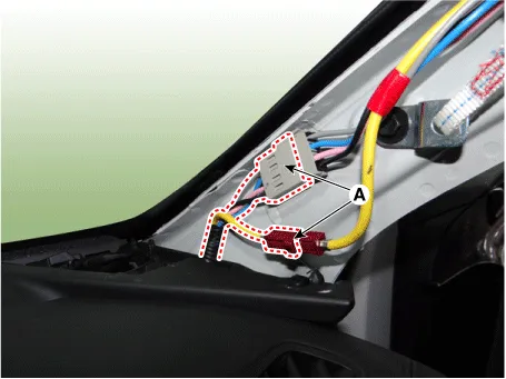
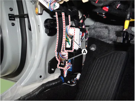
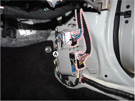
Loosen the front pillar mounting clips and separate the connectors (A). [LH]
[RH]
|
| 23. |
Separate the junction box connectors (A).
|
| 24. |
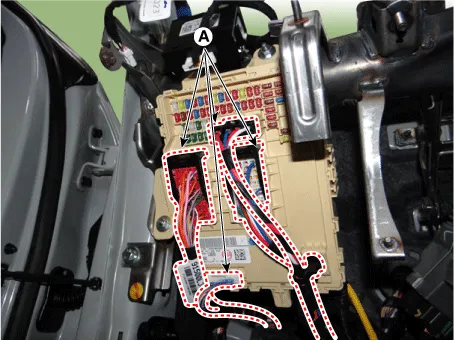
Separate the multi box connectors (A). [LH]
[RH]
|
| 25. |
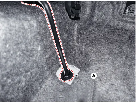
Remove the drain hose (A).
|
| 26. |
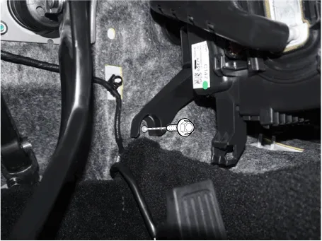
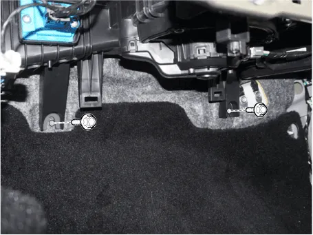
Remove the lower mounting bolt of the blower unit.
[LH]
[RH]
|
| 27. |
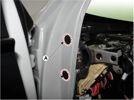
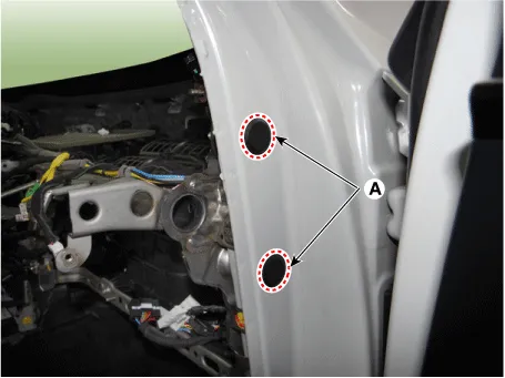
Remove the plug holes (A). |
| 28. |
Loosen the cowl cross bar side mounting bolts. [LH]
[RH]
|
| 29. |
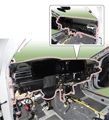
After loosening the bolts and nuts remove the crash pad and heater & blower unit assembly (A) together.
|
| 30. |
Remove the integrated body control unit. (Refer to Body Electrical System - "Integrated Body Control Unit (IBU)") |
| 31. |
Remove the heater control unit. (Refer to Heating,Ventilation And Air Conditioning - "Heater Control Unit") |
| 32. |
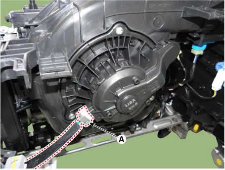
Separate the heater & blower unit connectors and wiring. [LH]
[RH]
|
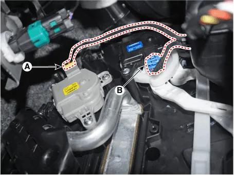
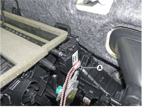
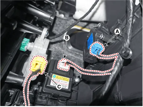
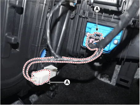
| 33. |
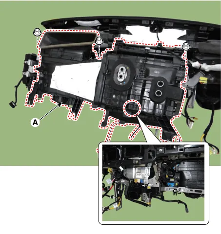
Loosen the mounting nuts, bolts and remove the heater & blower unit (A) from the crash pad.
|
| 34. |
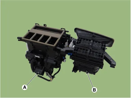
Loosen the mounting screws, separate the heater unit (A) and blower unit (B).
|
| 35. |
To install, reverse the removal procedure.
|

Repair procedures Replacement 1. Disconnect the negative (-) battery terminal. 2. Remove the heater and blower assembly.
Other information:
Kia Optima DL3 2019-2026 Service and Repair Manual: A/C Pressure Transducer
Description and operation Description The A/C Pressure Transducer (APT) converts the pressure value of high pressure line into voltage value after measuring it. By converted voltage value, engine ECU controls the cooling fan by operating it high speed or low speed.
Kia Optima DL3 2019-2026 Service and Repair Manual: Photo Sensor
Description and operation Description The photo sensor is located at the center of the defrost nozzles. The photo sensor contains a photovoltaic (sensitive to sunlight) diode. The solar radiation received by its light receiving portion, generates an electromotive force in proportion to the amount of radiation received which is
Categories
- Manuals Home
- Kia Optima Owners Manual
- Kia Optima Service Manual
- Air bag collision sensors
- Suspension System
- Brake System
- New on site
- Most important about car
