Kia Optima DL3: Floor Console / Floor Console Assembly
Components and components location
| Component Location |
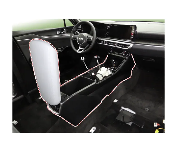
| 1. Front console assembly |
Repair procedures
| Replacement |
[SBC Console]
|

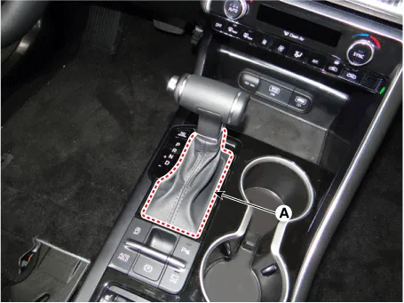
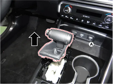
| 1. |
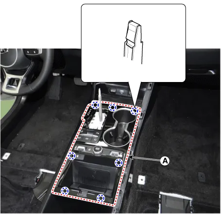
Remove the gear knob & boots (A) by pulling it upwards.
|
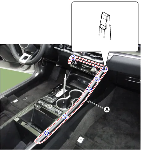
| 2. |
Using a screwdriver or remover, remove the console upper garnish (A).
|
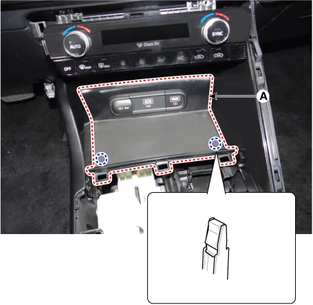
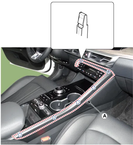
| 3. |
Using a screwdriver or remover, remove the console upper cover (A).
|
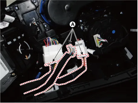
| 4. |
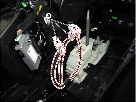
Disconnect the connectors (A).
|
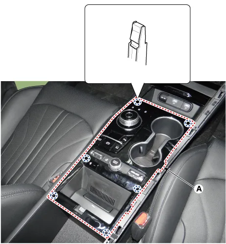
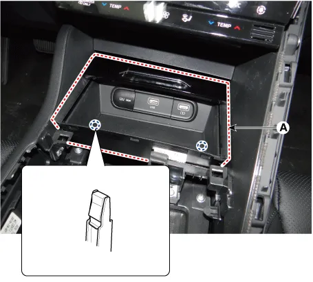
| 5. |
Using a screwdriver or remover, remove the console tray (A).
|
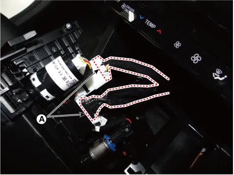
| 6. |
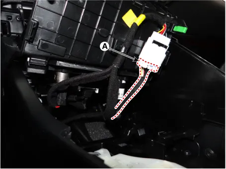
Disconnect the connector (A).
|
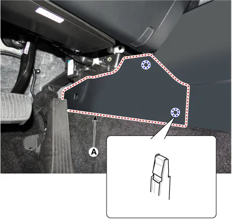
| 7. |
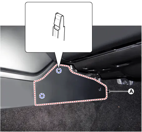
Remove the console side cover (A). [LH]
[RH]
|
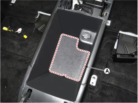
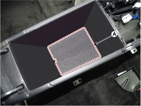
| 8. |
Remove the storage box pad (A).
|
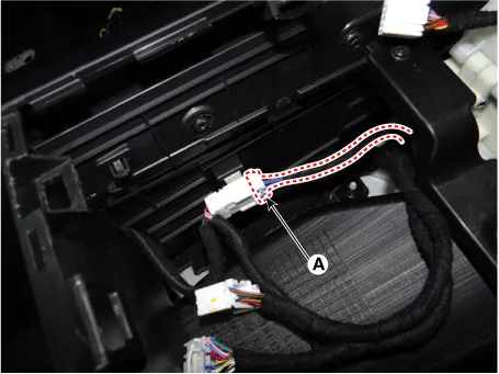
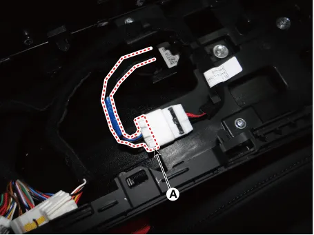
| 9. |
Disconnect the console main connector (A).
|
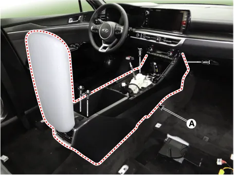
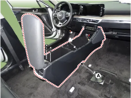
| 10. |
After loosening the mounting screws and bolts, remove the floor console assembly (A).
|
| 11. |
To install, reverse removal procedure.
|

[SBW Console]
|
| 1. |
Using a screwdriver or remover, remove the console upper garnish (A).
|
| 2. |
Using a screwdriver or remover, remove the console upper cover (A).
|
| 3. |
Disconnect the connectors (A).
|
| 4. |
Using a screwdriver or remover, remove the console tray (A).
|
| 5. |
Disconnect the connectors (A).
|
| 6. |
Remove the console side cover (A). [LH]
[RH]
|
| 7. |
Remove the storage box pad (A).
|
| 8. |
Disconnect the console main connector (A).
|
| 9. |
After loosening the mounting screws and bolts, remove the floor console assembly (A).
|
| 10. |
To install, reverse removal procedure.
|
Components and components location Components [SBC Console] 1. Console side cover [LH] 2. Console side cover [RH] 3.
Repair procedures Replacement • When removing with a flat-tip screwdriver or remover, wrap protective tape around the tools to prevent damage to components.
Other information:
Kia Optima DL3 2019-2026 Service and Repair Manual: Rear Glass Defogger Switch
Repair procedures Inspection 1. In the body electrical system, failure can be quickly diagnosed by using the vehicle diagnostic system (KDS). The diagnostic system (KDS) provides the following information. (1) Self diagnosis : Checking failure and code number (DTC).
Kia Optima DL3 2019-2026 Service and Repair Manual: Climate Control Air Filter
Description and operation Description The climate control air filter is located in the blower unit. It eliminates foreign materials and odor. The particle filter performs a role as an odor filter as well as a conventional dust filter to ensure comfortable interior environment.
Categories
- Manuals Home
- Kia Optima Owners Manual
- Kia Optima Service Manual
- Identification Numbers
- Restraint
- Heating, Ventilation and Air Conditioning
- New on site
- Most important about car
