
Kia Optima DL3: Front Radar System / Smart Cruise Control (SCC) Switch
Components and components location
| Components |
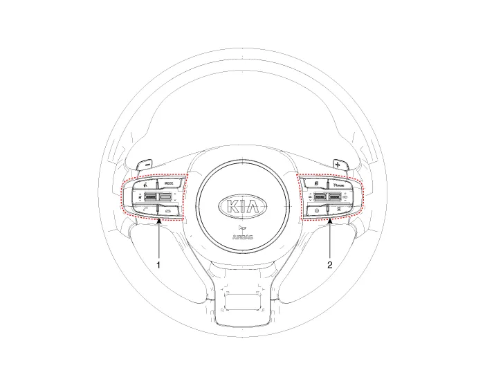
| 1. Left remote control switch
(Audio + Bluetooth + Voice) |
2. Right remote control switch
(Trip + SCC + LFA) |
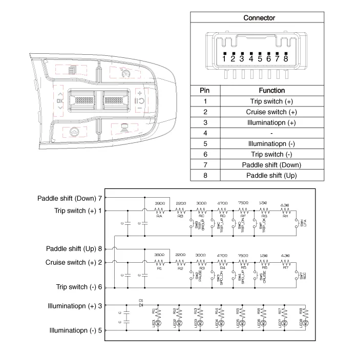
Schematic diagrams
| Circuit Diagram |
Repair procedures
| Removal |
| 1. |
Remove the steering wheel remote controller. [RH] (Refer to Body Electrical System - "Steering Wheel Remote Controller") |
| Installation |
| 1. |
Install in the reverse order of removal. |
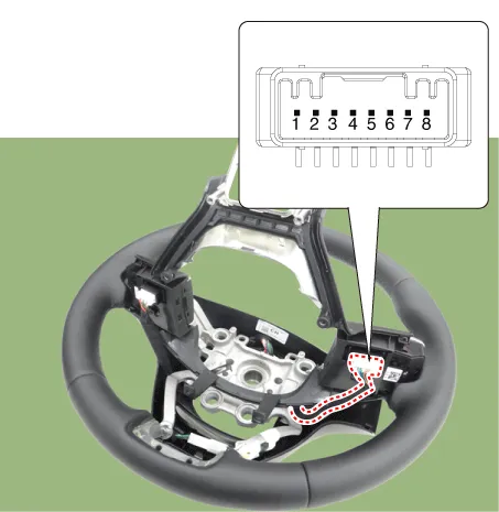
| Inspection |
| 1. |
Check for resistance between terminals in each switch position.
|
Specifications Specification Item Specification Power supply 12 V Operation voltage 9 - 16 V Installation angle Horizontal 0 ± 0.
Components and components location Components 1. Cluster (User setting menu) 2. Rear corner radar 3. Rear corner radar indicator Description and operation Description System Interface System Function • Blind-Spot Collision Warning (BCW) This system uses an audible warning and BCW signal on the mirror when sensing a vehicle in the blind spot area or when the vehicle is approaching at a high speed.
Other information:
Kia Optima DL3 2019-2026 Service and Repair Manual: Ventilated and Heated Seat Switch
Schematic diagrams Connector and Terminal Function [Front Seat] [Ventilation+Heater Type / Non-Heater Type] Pin Function Pin Function Ventilation+Heater Type Non-Heater Type Ventilation+Heater Type Non-Heater Type
Kia Optima DL3 2019-2026 Service and Repair Manual: Heater Unit
Components and components location Component Location 1. Heater unit assembly Compoents 1. Mode control actuator 2. Temperature control actuator [LH] 3. PTC Heater dummy 4.
Categories
- Manuals Home
- Kia Optima Owners Manual
- Kia Optima Service Manual
- Floor Console Assembly
- Timing Chain
- Air bag collision sensors
- New on site
- Most important about car
