Kia Optima DL3: Lighting System / Overhead Console Lamp
Schematic diagrams
| Connector and Terminal Function |
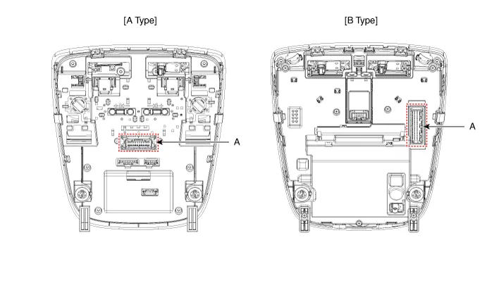
| [A Type] |
|
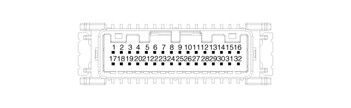
Connector A |
||
|
|
||
|
Pin |
E xcept Russia Region |
Russia only |
|
Function |
Function |
|
|
1 |
Battery (+) |
Battery (+) |
|
2 |
IGN1 (PAB) |
- |
|
3 |
IGN1 (SBR) |
- |
|
4 |
eCall PWM |
- |
|
5 |
- |
- |
|
6 |
eCall botton |
eCall botton |
|
7 |
- |
- |
|
8 |
eCall ground |
eCall ground |
|
9 |
Ground (Room, Door lamp) |
Ground (Room, Door lamp) |
|
10 |
PAB ON |
- |
|
11 |
PAB OFF |
- |
|
12 |
Ground (PAB, SBR) |
- |
|
13 |
LED (Red) |
LED (Red) |
|
14 |
LED (Green) |
LED (Green) |
|
15 |
ACC |
- |
|
16 |
Botton back light |
Botton back light |
|
17 |
- |
- |
|
18 |
Door (-) |
Door (-) |
|
19 |
Room lamp signal |
Room lamp signal |
|
20 |
SBR (Rear left) |
- |
|
21 |
SBR (Rear center) |
- |
|
22 |
SBR (Rear Right) |
- |
|
23 |
Ground (eCall MCU) |
- |
|
24 |
Ground (eCall LED) |
Ground (eCall LED) |

| [B Type] |
|
Connector A |
||
|
|
||
|
Pin |
Except Russia Region |
R ussia only |
|
Function |
Function |
|
|
1 |
Battery (+) |
Battery (+) |
|
2 |
IGN1 (PAB) |
IGN1 (PAB) |
|
3 |
- |
- |
|
4 |
eCall PWM |
- |
|
5 |
- |
- |
|
6 |
eCall botton |
eCall botton |
|
7 |
- |
- |
|
8 |
IGN1 (ETCS) |
IGN1 (ETCS) |
|
9 |
Ground (PAB, SBR, TMU) |
Ground (PAB, SBR, TMU) |
|
10 |
- |
- |
|
11 |
- |
- |
|
12 |
eCall ground |
eCall ground |
|
13 |
Ground (Room, Door lamp) |
Ground (Room, Door lamp) |
|
14 |
PAB ON |
PAB ON |
|
15 |
PAB OFF |
PAB OFF |
|
16 |
Door (-) |
Door (-) |
|
17 |
LED (Red) |
LED (Red) |
|
18 |
LED (Green) |
LED (Green) |
|
19 |
ACC |
- |
|
20 |
Botton back light |
Botton back light |
|
21 |
IGN1 (SBR) |
IGN1 (SBR) |
|
22 |
Room lamp signal |
Room lamp signal |
|
23 |
- |
- |
|
24 |
- |
- |
|
25 |
SBR (Rear left) |
SBR (Rear left) |
|
26 |
SBR (Rear center) |
SBR (Rear center) |
|
27 |
SBR (Rear Right) |
SBR (Rear Right) |
|
28 |
Ground (eCall MCU) |
Ground (eCall MCU) |
|
29 |
Ground (eCall LED) |
Ground (eCall LED) |
|
30 |
- |
- |
|
31 |
- |
- |
|
32 |
- |
- |
Repair procedures
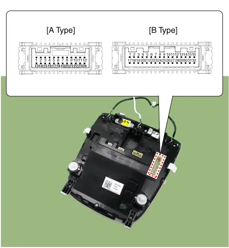
| Inspection |
| 1. |
Remove the overhead console lamp. (Refer to Lighting System - "Overhead Console Lamp") |
| 2. |
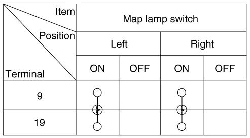
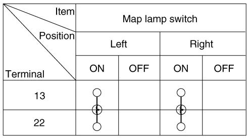
Check for continuity between terminals.
[A Type]
[B Type]
|
| Removal |
| 1. |
Disconnect the negative battery terminal. |
| 2. |
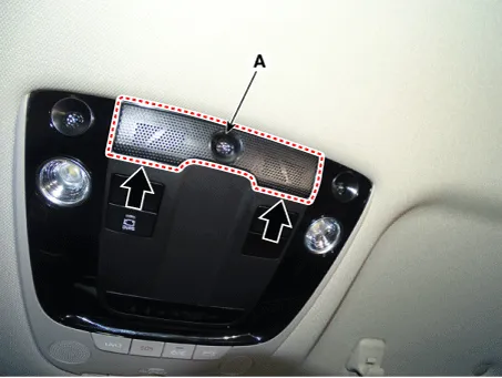
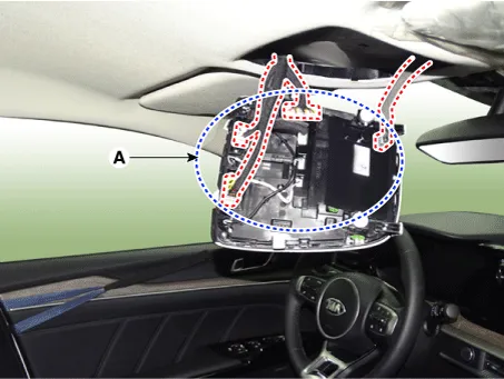
Remove the overhead console lamp mic grill (A) by using a flat-tip screwdriver or remover.
|
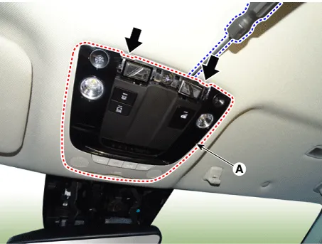
| 3. |
Remove the overhead console lamp (A) by using a flat-tip screwdriver or remover.
|

| 4. |
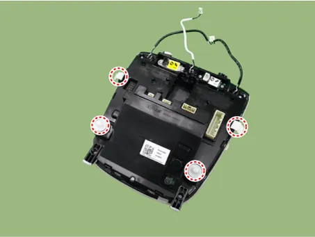
Disconnect the all connectors (A) from the overhead console lamp.
|
| Installation |
| 1. |
Install in the reverse of the removal. |
Repair procedures Removal 1. Disconnect the negative battery terminal. 2. Remove the trunk room lamp (A) by pressing the hook.
Components and components location Component Location 1. Tail lamp 2. Stop lamp 3. Tail/Stop lamp 4. Back up lamp 5.
Other information:
Kia Optima DL3 2019-2026 Service and Repair Manual: Integrated Body Control Unit (IBU)
Components and components location Component Location 1. Integrated Body Control Unit (IBU) Schematic diagrams Connector and Terminal Function [Non-Smart key] Pin Function Connector A Connector B
Kia Optima DL3 2019-2026 Service and Repair Manual: Power Door Lock Module
Repair procedures Inspection When prying with a flat-tip screwdriver or use a prying trim tool, wrap it with protective tape, and apply protective tape around the related parts, to prevent damage.
Categories
- Manuals Home
- Kia Optima Owners Manual
- Kia Optima Service Manual
- Floor Console Assembly
- Battery
- Engine Mechanical System
- New on site
- Most important about car
