Kia Optima DL3: Wiper/Washer / Washer Motor
Repair procedures
| Inspection |
Washer Motor
| 1. |
With the washer motor connected to the reservoir tank, fill the reservoir tank with water.
|

| 2. |
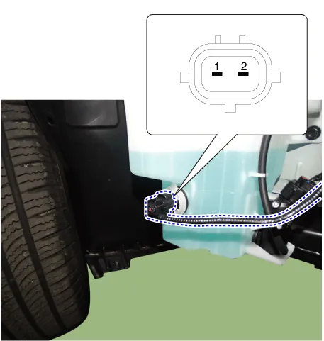
Connect positive (+) battery cables to terminal 2 and negative (-) battery cables to terminal 1 respectively. |
| 3. |
Check that the motor operates normally and the washer motor runs and water sprays from the front nozzles. |
| 4. |
If they are abnormal, replace the washer motor.
|

Washer Fluid Level Sensor
| 1. |
Disconnect the negative battery terminal. |
| 2. |
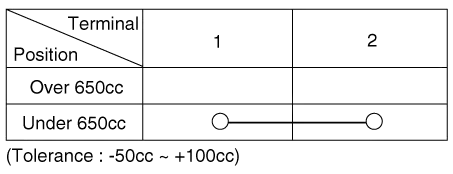
Drain the washer fluid less than 650 cc. |
| 3. |
Check for continuity between the No. 1 and No.2 terminal in each float position. There should be continuity when the float is down. There should be no continuity when the float is up. |
| 4. |
If the continuity is not as specified, replace the washer fluid level switch
|
| Removal |
Washer Motor
| 1. |
Disconnect the negative battery terminal. |
| 2. |
Remove the engine room under cover. G 2.0 NU MPI (Refer to Engine Mechanical System - "Engine Room Under Cover") G 2.5 GDI THETA II (Refer to Engine Mechanical System - "Engine Room Under Cover") |
| 3. |
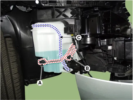
Disconnect the connector (B) and then remove the washer motor (C) after separating the nozzles (A).
|

Washer Fluid Level Sensor
| 1. |
Disconnect the negative battery terminal. |
| 2. |
Remove the engine room under cover. G 2.0 NU MPI (Refer to Engine Mechanical System - "Engine Room Under Cover") G 2.5 GDI THETA II (Refer to Engine Mechanical System - "Engine Room Under Cover") |
| 3. |
Remove the washer fluid level sensor (A) after disconnecting the connector (B).
|

Reservoir
| 1. |
Disconnect the negative battery terminal. |
| 2. |
Remove the engine room under cover. G 2.0 NU MPI (Refer to Engine Mechanical System - "Engine Room Under Cover") G 2.5 GDI THETA II (Refer to Engine Mechanical System - "Engine Room Under Cover") |
| 3. |
Remove the right side front wheel guard. (Refer to Body - "Front Wheel Guard") |
| 4. |
Remove the reservoir.
|

| Installation |
| 1. |
Install in the reverse order of the removal. |
Repair procedures Replacement 1. If wiper switch needs to be replaced, replace the multifunction switch assembly. (Refer to Body Electrical System - "Multifunction Switch")
Schematic diagrams Connector and Terminal Function
Other information:
Kia Optima DL3 2019-2026 Service and Repair Manual: Fog Lamp
Repair procedures Removal Front Fog Lamp 1. Disconnect the negative battery terminal. 2. Remove the front bumper assembly. (Refer to Body - "Front Bumper Assembly") 3.
Kia Optima DL3 2019-2026 Service and Repair Manual: Blower Resistor
Repair procedures Inspection 1. Measure the resistance between the terminals. 2. measured resistance is not within specification, the blower resistor must be replaced. (After removing the resistor) (1) Pin No 1.
Categories
- Manuals Home
- Kia Optima Owners Manual
- Kia Optima Service Manual
- Battery
- Rear Brake Disc
- Heating, Ventilation and Air Conditioning
- New on site
- Most important about car
