Kia Optima DL3: Body Electrical System / Multifunction Switch
Specifications
| Specifications |
|
Items |
Specifications |
|
|
Rated voltage |
Front fog lamp switch |
5 V |
|
Lighting |
||
|
Auto lighting |
||
|
Dimmer & Passing |
||
|
Turn signal lamp |
||
|
Wiper |
||
|
Washer |
14.5 V |
|
Schematic diagrams
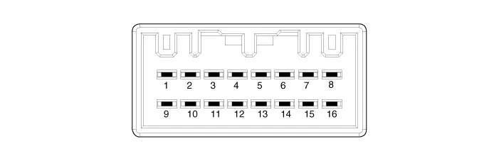
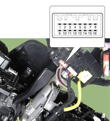
| Connector and Terminal Function |
|
Connector A |
||
|
|
||
|
Pin |
Standard |
R-MDPS |
|
1 |
- |
- |
|
2 |
Headlamp low back up signal |
Headlamp low back up signal |
|
3 |
Front wiper INT volume signal |
- |
|
4 |
Ground |
- |
|
5 |
Ground (IBU) |
Ground |
|
6 |
Front wiper switch signal |
- |
|
7 |
Front wiper low back up signal |
Front wiper low back up signal |
|
8 |
IGN2 |
IGN2 |
|
9 |
Front washer motor switch power |
Front washer motor switch power |
|
10 |
Light switch signal |
C-CAN (High) |
|
11 |
- |
C-CAN (Low) |
|
12 |
Fog lamp switch signal |
IGN1 |
|
13 |
Headlamp passing/high beam switch signal |
- |
|
14 |
Turn signal switch (LH) |
B-CAN (High) |
|
15 |
Turn signal switch (RH) |
B-CAN (Low) |
|
16 |
- |
Battery (+) |
Repair procedures
| Removal |
| 1. |
Disconnect the negative battery terminal. |
| 2. |
Remove the steering column upper and lower shrouds. (Refer to Body - "Steering Column Shroud Panel") |
| 3. |
Remove the steering wheel. (Refer to Steering System - "Steering Wheel") |
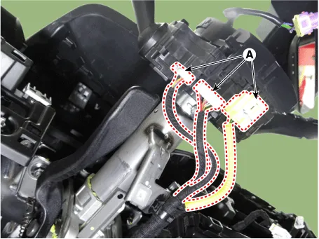
| 4. |
Disconnect the all connector (A) from the multifunction switch.
|
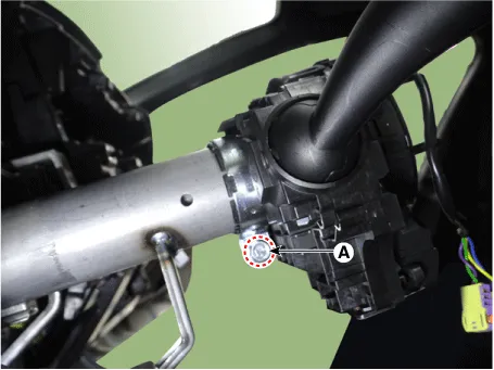
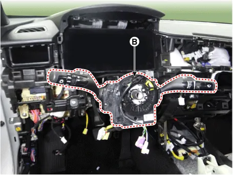
| 5. |
Remove the multifunction switch (B) by loosening the mounting bolt (A).
|

| Installation |
| 1. |
Install in the reverse order of removal. |
| Inspection |
Multifunction Switch Inspection
| 1. |
Disconnect the negative battery terminal. |
| 2. |
Remove the steering column upper and lower shrouds. (Refer to Body - "Steering Column Shroud Panel") |
| 3. |
Check for continuity between the terminals in each switch position as shown below.
|
Diagnosis With KDS
| 1. |
In the body electrical system, failure can be quickly diagnosed by using the vehicle diagnostic system (KDS). The diagnostic system (KDS) provides the following information.
|
| 2. |
Select the "Car model" and the 'IBU-BCM' to be checked in order to check the vehicle with the tester.
|
| 3. |
Select the 'Current Data' menu to search the current state of the input/output data. |
| 4. |
To force actuate the input value of the module to be checked, select option 'Actuation Test'. |
Schematic diagrams Connector and Terminal function Repair procedures Removal When removing with a flat-tip screwdriver or remover, wrap protective tape around the tools to prevent damage to components.
Components and components location Component Location 1. Panorama sunroof assembly 2. Panorama sunroof switch 3.
Other information:
Kia Optima DL3 2019-2026 Service and Repair Manual: Ambient Temperature Sensor
Description and operation Description The ambient temperature sensor is located at the front of the condenser and detects ambient air temperature. It is a negative type thermistor; resistance will increase with lower temperature, and decrease with higher temperature.
Kia Optima DL3 2019-2026 Service and Repair Manual: Evaporator Core
Repair procedures Replacement 1. Disconnect the negative (-) battery terminal. 2. Remove the heater and blower assembly. (Refer to Heater - "Heater Unit") 3. Loosen the mounting screws, lock pin and remove the evaporator core cover (A).
Categories
- Manuals Home
- Kia Optima Owners Manual
- Kia Optima Service Manual
- Engine Mechanical System
- Engine Control / Fuel System
- Floor Console Assembly
- New on site
- Most important about car
