Kia Optima DL3: Body Electrical System
General information
| General Troubleshooting Information |
Before Troubleshooting
| 1. |
Check applicable fuses in the appropriate fuse/relay box. |
| 2. |
Check the battery for damage, State Of Charge (SOC), cleanliness and tight connections.
|

| 3. |
Check the alternator belt tension. |
Handling Connectors
| 1. |
Make sure the connectors are clean and have no loose wire terminals. |
| 2. |
Make sure multiple cavity connectors are packed with grease (except watertight and oxygen sensor connectors). |
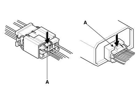
| 3. |
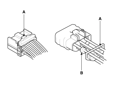
All connectors have push-down release type locks (A).
|
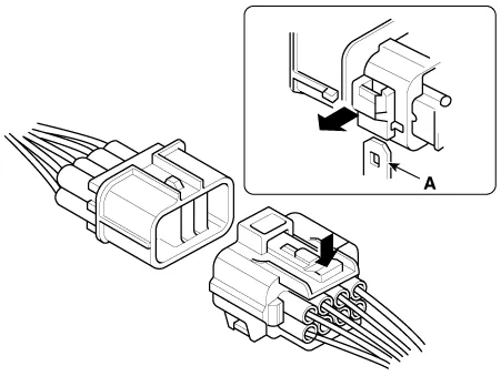
| 4. |
Some connectors have a clip on their side used to attach them to a mount bracket on the body or on another component. This clip has a pull type lock. |
| 5. |
Some mounted connectors cannot be disconnected unless you first release the lock and remove the connector from its mounting bracket (A).
|
| 6. |
Never try to disconnect connectors by pulling on their wires; pull on the connector halves instead. |
| 7. |
Always reinstall plastic covers.
|
| 8. |
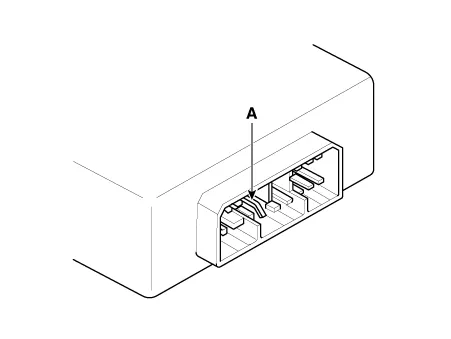
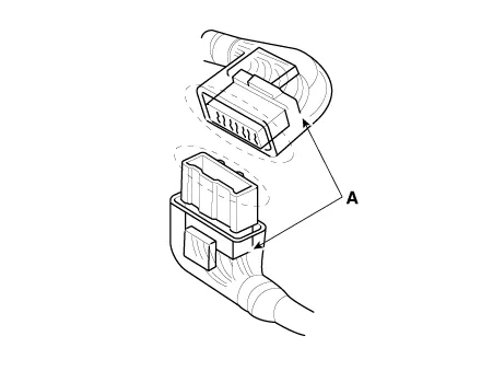
Before connecting connectors, make sure the terminals (A) are in place and not bent.
|
| 9. |
Check for loose retainer (A) and rubber seals (B).
|
| 10. |
The back of some connectors are packed with grease. Add grease if necessary. If the grease (A) is contaminated, replace it.
|
| 11. |
Insert the connector all the way and make sure it is securely locked. |
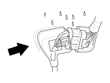
| 12. |
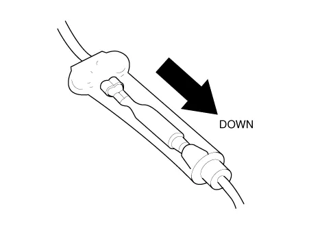
Position wires so that the open end of the cover faces down.
|
Handling Wires And Harnesses
| 1. |
Secure wires and wire harnesses to the frame with their respective wire ties at the designated locations. |
| 2. |
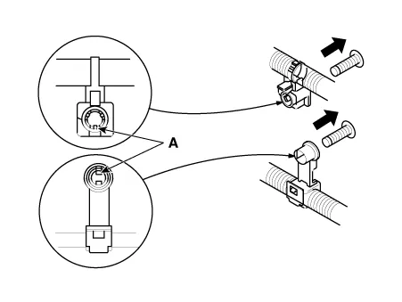
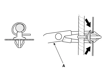
Remove clips carefully; don't damage their locks (A).
|
| 3. |
Slip pliers (A) under the clip base and through the hole at an angle, and then squeeze the expansion tabs to release the clip.
|
| 4. |
After installing harness clips, make sure the harness doesn't interfere with any moving parts. |
| 5. |
Keep wire harnesses away from exhaust pipes and other hot parts, from sharp edges of brackets and holes, and from exposed screws and bolts. |
| 6. |
Seat grommets in their grooves properly (A). Do not leave grommets distorted (B).
|

Testing and Repairing
| 1. |
Do not use wires or harnesses with broken insulation. Replace them or repair them by wrapping the damage wire with electrical tape. |
| 2. |
After installing parts, make sure that no wires are pinched under them. |
| 3. |
When using electrical test equipment, follow the manufacturer's instructions and those described in this manual. |
| 4. |
If possible, insert the remover tool from the wire side (except waterproof connector).
|
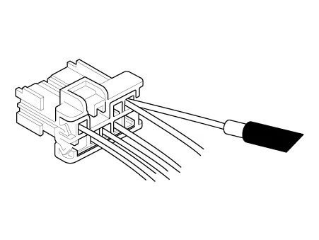
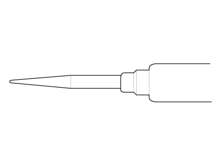
| 5. |
Use a probe with a tapered tip. Refer to the user's guide in the wiring repair kit (Pub No. : TRK 015.)
|
Five-step Troubleshooting
| 1. |
Verify the complaint Turn on all the components in the problem circuit to verify the customer complaint. Note the symptoms. Do not begin disassembling or testing until you have narrowed down the problem area. |
| 2. |
Analyze the schematic Look up the schematic for the problem circuit. Determine how the circuit is supposed to work by tracing the current paths from the power feed through the circuit components to ground. If several circuits fail at the same time, the fuse or ground is a likely cause. Based on the symptoms and your understanding of the circuit operation, identify one or more possible causes of the problem. |
| 3. |
Isolate the problem by testing the circuit. Make circuit tests to check the diagnosis you made in step 2. Keep in mind that a logical, simple procedure is the key to efficient troubleshooting. Test for the most likely cause of failure first. Try to make tests at points that are easily accessible. |
| 4. |
Fix the problem Once the specific problem is identified, make the repair. Be sure to use proper tools and safe procedures. |
| 5. |
Make sure the circuit works Turn on all components in the repaired circuit in all modes to make sure you've fixed the entire problem. If the problem was a blown fuse, be sure to test all of the circuits on the fuse. Make sure no new problems turn up and the original problem does not reoccur. |
Installation of the transmitting device.
Electronically controlled computers are designed not to be interrupted by other radio signals, but it can be affected by a remote control of even at less than 25 W output if the antenna or cable of a remote control is wired near the computer. To prevent this, follow the directions below.
| 1. |
Install the antenna on the roof or rear bumper. |
| 2. |
Keep the antenna cables at least 200 mm away from the computer or wiring as they transmit radio signals. |
| 3. |
Decrease the standing-wave ratio by using proper antennas and cables. |
| 4. |
Do not install remote control with high output signals. |
| 5. |
After installing the remote control, check the engine by generating radio signals with the engine at idle.
|
Power Window and Sunroof Reset
If negative (-) battery cable was removed or fuse was replaced while opening/closing the power window or sunroof, perform initialization again as the default value of motor is erased.
|
System |
Resetting |
||||||||||||||||
|
Auto up/down window |
|
||||||||||||||||
|
Sunroof |
|

Trip computer, Clock and Audio Reset
When reconnecting the battery cable after disconnecting, recharging battery after discharged or installing the memory fuse located on the driver's side panel after removing, be sure to reset systems mentioned on the table below.
In addition, when replacing or reinstalling the fuses after removing, reset according to the table below.
|
System |
Resetting |
|
Trip computer |
If the battery has been disconnected, the trip computer will be reinitialized
after reconnecting the battery. Explain this to customer. |
|
Clock |
If the battery terminals or related fuses have been disconnected, you must
reset the time in the audio head unit. (Refer to "Audio" in owner's manual.)
|
|
Audio |
If the battery has been disconnected, the customer's preset radio stations
will be initialized. Record the customer's preset radio stations prior to
servicing, and set the customer's preset radio stations into the audio after
service. |
- Auto Lighting Control System
- Audio/AVN System
- A/V Navigation
- Audio
- Speaker
- External Amp
- Antenna
- Steering Wheel Remote Controller (SWRC)
- Multimedia Jack
- Mic
- Button Engine Start System
- Charging System
- Electro Chromic Inside Rear View Mirror
- Emergency Call System
- Fuses And Relays
- Fuel Filler Door
- Headlamp Leveling System
- Head Up Display System
- Horn
- Ignition Switch Assembly
- Indicators And Gauges
- Integrated Memory Seat (IMS)
- Integrated Body Control Unit (IBU)
- Keyless Entry And Burglar Alarm
- Lighting System
- Fog Lamp
- Hazard Lamp Switch
- Headlamps
- High Mounted Stop Lamp
- License Lamps
- Trunk Room Lamp
- Overhead Console Lamp
- Rear Combination Lamp
- Rheostat
- Room Lamp
- Vanity Lamp
- Personal Lamp
- Mood Lamp Unit
- Multifunction Switch
- Panorama Sunroof
- Power Door Locks
- Power Door Mirrors
- Power Windows
- Rear Glass Defogger
- Seat Electrical
- Heated Seats Only
- Ventilated and Heated Seat Switch
- Ventilated and Heated Seat
- Lumbar Support System
- Power Seat Control Switch
- Power Seat Motor
- Walk-in Switch
- Relaxion Comfort Seat
- Smart Key System
- Wiper/Washer
Repair procedures Replacement • When installing the belt, make sure not to damage the retractor.
Specifications Specifications Items Specifications Rated voltage DC +5 V Load Max.
Other information:
Kia Optima DL3 2019-2026 Service and Repair Manual: Panorama Sunroof Motor
Schematic diagrams Connector and Terminal Function Repair procedures Inspection 1. Disconnect the negative battery terminal. 2. Remove the rear pillar trim [LH]. (Refer to Body - "Rear Pillar Trim") 3.
Kia Optima DL3 2019-2026 Service and Repair Manual: Rear Glass Defogger Switch
Repair procedures Inspection 1. In the body electrical system, failure can be quickly diagnosed by using the vehicle diagnostic system (KDS). The diagnostic system (KDS) provides the following information. (1) Self diagnosis : Checking failure and code number (DTC).
Categories
- Manuals Home
- Kia Optima Owners Manual
- Kia Optima Service Manual
- Front Axle Assembly
- Timing Chain
- Cooling System
- New on site
- Most important about car
