Kia Optima DL3: Blower / Power Mosfet
Description and operation
| Description |
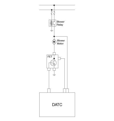
It is installed to the DATC and adjusts the fan rpm by precisely controlling the voltage applied to the blower motor.
Repair procedures
| Inspection |
| 1. |
Turn the ignition switch ON. |
| 2. |
Manually operate the control switch and measure the voltage of the blower motor. |
| 3. |
Select the control switch to raise the voltage until high speed.
|
| Replacement |
| 1. |
Disconnect the negative (-) battery terminal. |
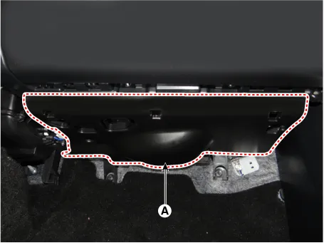
| 2. |
Remove the crash pad under cover (A).
|
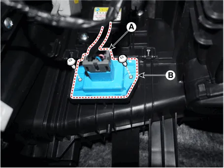
| 3. |
Separate the connector (A), loosen the mounting screws and remove the power mosfet (B).
|
| 4. |
To install, reverse the removal procedure. |
Repair procedures Inspection 1. Measure the resistance between the terminals. 2. measured resistance is not within specification, the blower resistor must be replaced.
Description and operation Description The climate control air filter is located in the blower unit. It eliminates foreign materials and odor.
Other information:
Kia Optima DL3 2019-2026 Service and Repair Manual: Power Seat Motor
Components and components location Components 1. Lumbar support motor 2. Reclining motor 3. Front height motor 4. Rear height motor 5. Slide motor Repair procedures Inspection 1.
Kia Optima DL3 2019-2026 Service and Repair Manual: Heater Core
Repair procedures Replacement 1. Disconnect the negative (-) battery terminal. 2. Remove the heater and blower assembly. (Refer to Heater - "Heater Unit") 3. Loosen the mounting screws and remove the heater core cover (A).
Categories
- Manuals Home
- Kia Optima Owners Manual
- Kia Optima Service Manual
- Headlamps
- Brake System
- Rear Brake Disc
- New on site
- Most important about car
