Kia Optima DL3: Blower / Blower Resistor
Repair procedures
| Inspection |
| 1. |
Measure the resistance between the terminals. |
| 2. |
measured resistance is not within specification, the blower resistor must be replaced. (After removing the resistor)
|


| Replacement |
| 1. |
Disconnect the negative (-) battery terminal. |
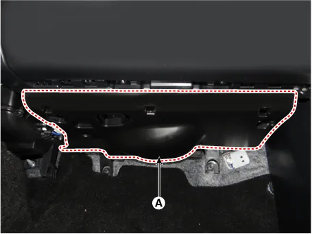
| 2. |
Remove the crash pad under cover (A).
|
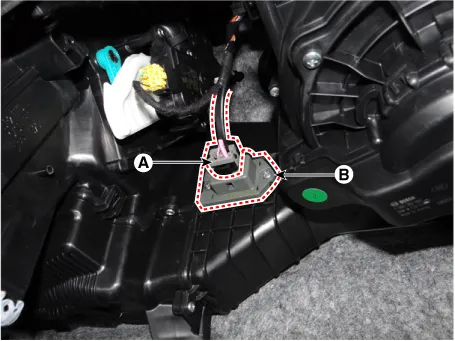
| 3. |
Disconnect the connector (A) and then remove the blower resistor (B) after loosening the mounting screws.
|
Repair procedures Inspection 1. Connect the battery voltage and check the blower motor rotation. 2.
Description and operation Description It is installed to the DATC and adjusts the fan rpm by precisely controlling the voltage applied to the blower motor.
Other information:
Kia Optima DL3 2019-2026 Service and Repair Manual: Refrigerant Line
Components and components location Components Location 1. Suction & Liquid tube assembly 2. Discharge hose Repair procedures Replacement 1. If the compressor is marginally operable, run the engine at idle speed, and let the air conditioning work for a few minute
Kia Optima DL3 2019-2026 Service and Repair Manual: Power Mosfet
Description and operation Description It is installed to the DATC and adjusts the fan rpm by precisely controlling the voltage applied to the blower motor. Repair procedures Inspection 1. Turn the ignition switch ON.
Categories
- Manuals Home
- Kia Optima Owners Manual
- Kia Optima Service Manual
- Battery
- Engine Control / Fuel System
- Identification Numbers
- New on site
- Most important about car
