Kia Optima DL3: Engine Control System / Accelerator Position Sensor (APS)
Specifications
| Specification |
|
Accelerator |
Output Voltage (V) [Vref = 5.0V] |
|
|
Position |
APS1 |
APS2 |
|
C.T |
0.7 - 0.8 |
0.33 - 0.43 |
|
W.O.T |
4.13 - 4.22 |
2.04 - 2.13 |
Description and operation
| Description |
| • |
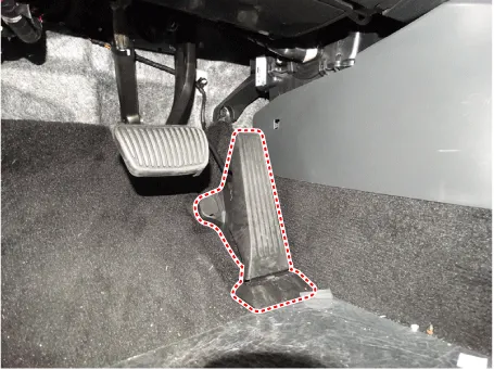
Accelerator Position Sensor (APS) is installed on the accelerator pedal module and detects the rotation angle of the accelerator pedal. |
| • |
The APS is one of the most important sensors in engine control system, so it consists of the two sensors which adapt individual sensor power and ground line. |
| • |
The second sensor monitors the first sensor and its output voltage is half of the first one. |
| • |
If the ratio of the sensor 1 and 2 is out of the range (approximately 1/2), the diagnostic system judges that it is abnormal. |
Schematic diagrams
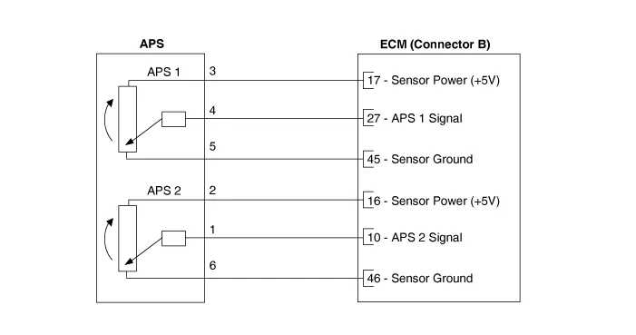
| Circuit Diagram |
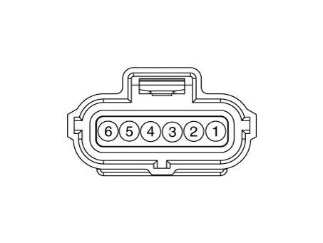
Harness Connector
Repair procedures
| Inspection |
| 1. |
The engine control system can be more quickly diagnosed for troubles by using the vehicle diagnostic system (KDS). (Refer to "DTC guide") KDS provides the following information.
|
| Component Inspection |
| 1. |
Connect the KDS on the Data Link Connector (DLC). |
| 2. |
Turn the ignition switch ON. |
| 3. |
Measure the output voltage of the APS 1 and 2 at C.T and W.O.T.
|
||||||||||||
| Removal |
| 1. |
Disconnect the negative battery terminal. |
| 2. |
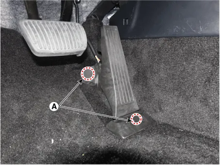
Open the mounting cap (A).
|
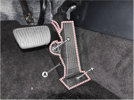
| 3. |
Remove the accelerator pedal module (A) after loosening the mounting bolts.
|
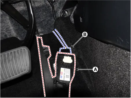
| 4. |
Remove the connector (A) from the accelerator pedal module (B).
|
| Installation |
|

| 1. |
Install in the reverse order of removal. |
Description and operation Description • Heated Oxygen Sensor (HO2S), consisting of zirconium and alumina, is installed on both upstream and downstream of the Manifold Catalytic Converter (MCC) to detect the air/fuel ratio and send it to the ECM.
Specifications Specification Item Specification Coil Resistance (Ω) 9.4 - 10.4 [20°C(68°F)] Description and operation Description • Continuous Variable Valve Timing (CVVT) system advances or retards the valve timing of the intake and exhaust valve in accordance with the ECM control signal which is calculated by the engine speed and load.
Other information:
Kia Optima DL3 2019-2026 Service and Repair Manual: Power Door Locks
C
Kia Optima DL3 2019-2026 Service and Repair Manual: Heater & A/C Control Unit (Manual)
Components and components location Components Connector Pin Function [Connector A] Pin NO Funtion Pin NO Funtion 1 Battery (+) 21 IGN2 2 ILL+ (TAIL) 22 IGN1
Categories
- Manuals Home
- Kia Optima Owners Manual
- Kia Optima Service Manual
- Floor Console Assembly
- Cooling System
- Front Axle Assembly
- New on site
- Most important about car
