Kia Optima DL3: Engine Control System / Heated Oxygen Sensor (HO2S)
Description and operation
| Description |
| • |
Heated Oxygen Sensor (HO2S), consisting of zirconium and alumina, is installed on both upstream and downstream of the Manifold Catalytic Converter (MCC) to detect the air/fuel ratio and send it to the ECM. |
| • |
In order that this sensor operates properly, the temperature of the sensor tip must be higher than 370°C (698°F). For this reason, a heater controlled by the ECM duty signal, is built into the sensor. When the exhaust gas temperature is lower than the specified value, the heater warms the sensor tip. |
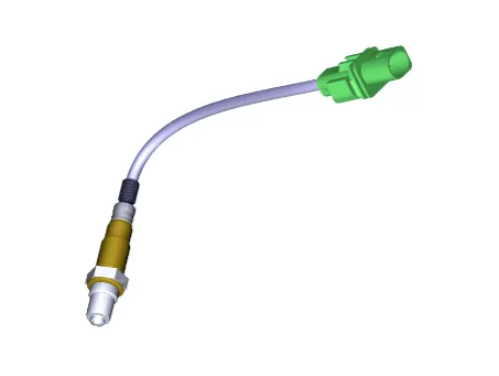
[Front Heated Oxygen Sensor]
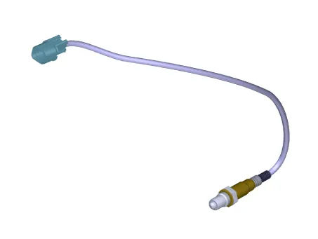
[Rear Heated Oxygen Sensor]
Components and components location
| Components Location |
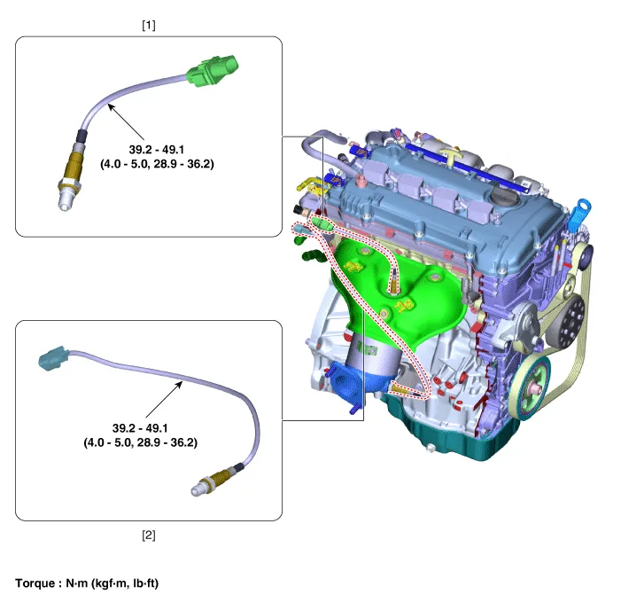
| 1. Front Heated Oxygen Sensor
|
2. Rear Heated Oxygen Sensor
|
Schematic diagrams
| Circuit Diagram |
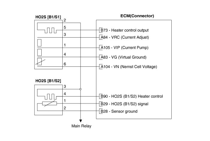
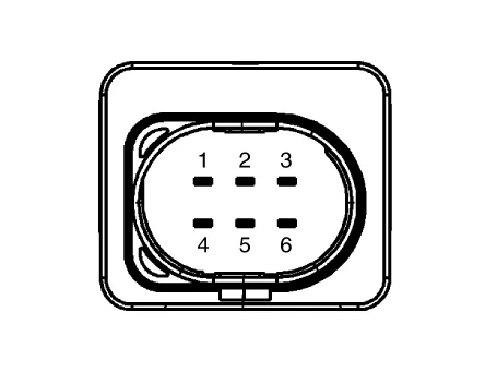
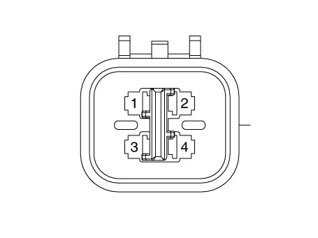
Harness Connector
[Front Heated Oxygen Sensor]
[Rear Heated Oxygen Sensor]
Repair procedures
| Inspection |
| 1. |
The engine control system can be more quickly diagnosed for troubles by using the vehicle diagnostic system (KDS). (Refer to "DTC guide") KDS provides the following information.
|
| Component Inspection |
| 1. |
Check signal waveform of HO2S using a KDS.
|
| Removal |
| [Front Heated Oxygen Sensor] |
| 1. |
Disconnect the negative battery terminal. |
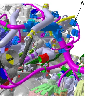
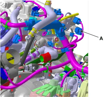
| 2. |
Disconnect the connector (A).
|
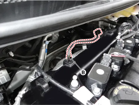
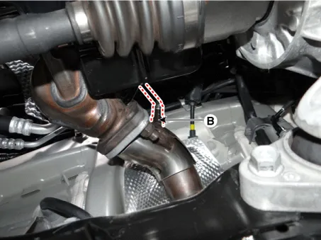
| 3. |
Remove the heated oxygen sensor (B) by using the SST (09392-1Y100)
|
| [Rear Heated Oxygen Sensor] |
| 1. |
Disconnect the negative battery terminal. |
| 2. |
Disconnect the heated oxygen sensor connector (A).
|
| 3. |
Remove the heated oxygen sensor (B) by using the SST (09392-1Y100)
|
| Installation |
|

| 1. |
Install in the reverse order of removal. |
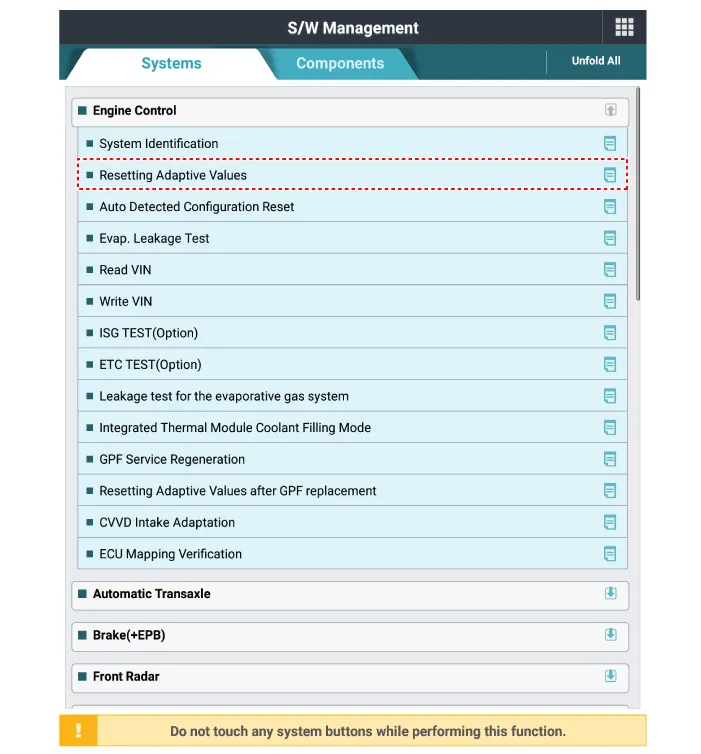
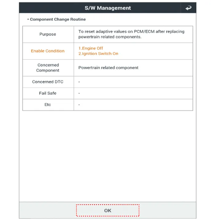
| 2. |
Reset the ECM adaptive value after replacing the heated oxygen sensor.
|
Specifications Specification Item Specification Capacitance (pF) 850 - 1,150 Description and operation Description • Knocking is a condition characterized by undesirable vibration and noise and can cause engine damage.
Specifications Specification Accelerator Output Voltage (V) [Vref = 5.0V] Position APS1 APS2 C.
Other information:
Kia Optima DL3 2019-2026 Service and Repair Manual: Power Door Mirrors
C
Kia Optima DL3 2019-2026 Service and Repair Manual: Rear Glass Defogger Printed Heater
Repair procedures Inspection • Wrap tin foil around the end of the voltmeter test lead to prevent damaging the heater line. Apply pressure on the tin foil with hand and move the tin foil along the grid line to check for open circ
Categories
- Manuals Home
- Kia Optima Owners Manual
- Kia Optima Service Manual
- Body Electrical System
- Charging System
- Brake System
- New on site
- Most important about car
