Kia Optima DL3: Audio/AVN System / Antenna
Components and components location
| Components Location |
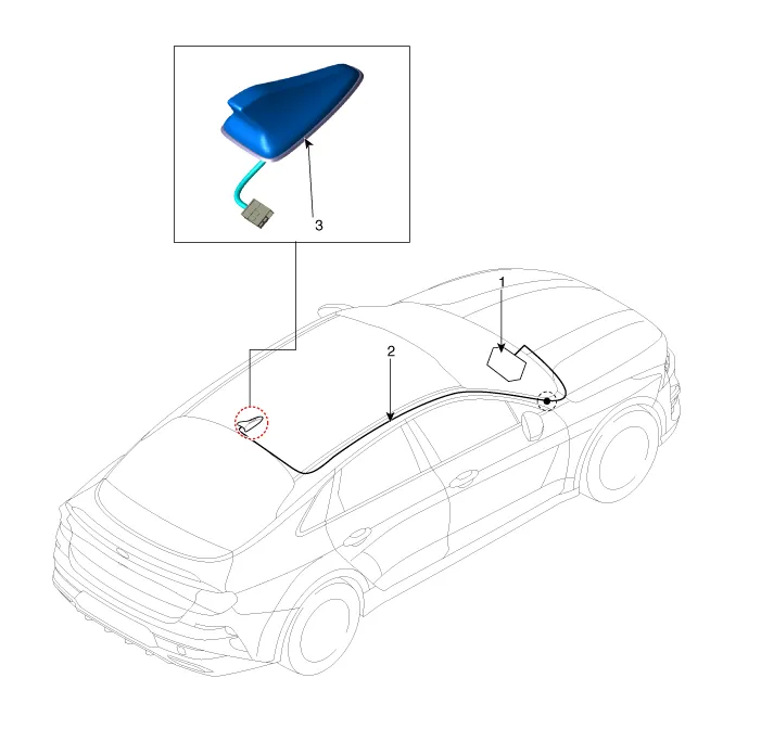
| 1. Audio/AVN head unit 2. Antenna feeder cable |
3. Roof antenna |
Repair procedures
| Removal |
| 1. |
Disconnect the negative battery terminal. |
| 2. |
Remove the roof trim assembly. (Refer to Body - "Roof Trim Assembly") |
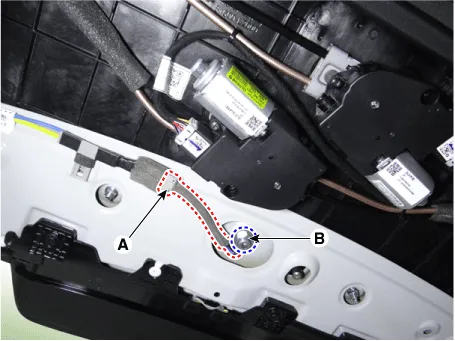
| 3. |
Disconnect the roof antenna connector (A). |
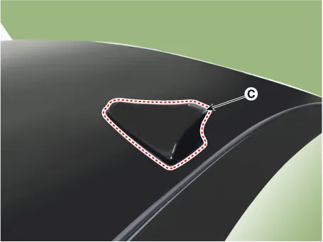
| 4. |
Remove the roof antenna (C) by loosening the mounting nut (B).
|
| Installation |
| 1. |
Install in the reverse order of removal. |
Components and components location Component Location 1. External amp Schematic diagrams Connector and Terminal Function Pin Function Connector A Connector B 1 Battery (+) Right front door tweeter speaker (+) 2 Battery (+) Left front door tweeter speaker (+) 3 Battery (+) Sub woofer speaker (+) 4 Battery (+) - 5 - - 6 MM-CAN (High) - 7 MM-CAN (Low) Amplifier navigation voice (+) 8 ACC - 9 - - 10 - - 11 - - 12 Right surround speaker (+) Right rear door speaker (+) 13 Left surround speaker (+) Left rear door speaker (+) 14 Right midrange speaker (+) Center speaker(+) 15 Left midrange speaker (+) - 16 Ground Right front door tweeter speaker (-) 17 Ground Left front door tweeter speaker (-) 18 Ground Sub woofer speaker (-) 19 Ground - 20 Amplifier SPDIF (High) - 21 Amplifier SPDIF (Low) Amplifier navigation voice (-) 22 Amplifier SPDIF (Ground) - 23 - - 24 IGN1 - 25 Right surround speaker (-) Right rear door speaker (-) 26 Left surround speaker (-) Left rear door speaker (-) 27 Right midrange speaker (-) Center speaker (-) 28 Left midrange speaker (-) - Repair procedures Inspection • Warning and guide sounds regarding engine start and driving are generated by the external amplifier.
Components and components location Components 1. Left remote control switch (Audio + Bluetooth + Voice) 2. Right remote control switch (Trip + SCC + LFA) Schematic diagrams Circuit Diagram [Audio + Bluetooth + Voice] [Trip + SCC + LFA] Repair procedures Removal 1.
Other information:
Kia Optima DL3 2019-2026 Service and Repair Manual: Rear Combination Lamp
Components and components location Component Location 1. Tail lamp 2. Stop lamp 3. Tail/Stop lamp 4. Back up lamp 5. Turn signal lamp Schematic diagrams Connector and Terminal Function [A Type] Pin Function Center Ou
Kia Optima DL3 2019-2026 Service and Repair Manual: Heated Seats Only
Components and components location Components Front Seat Heater 1. Front seat back heater 2. Front seat cushion heater 3. Front seat heater unit / ventilation unit Rear Seat Heater 1.
Categories
- Manuals Home
- Kia Optima Owners Manual
- Kia Optima Service Manual
- Suspension System
- Timing Chain
- Engine Mechanical System
- New on site
- Most important about car
