Kia Optima DL3: Audio/AVN System / External Amp
Components and components location
| Component Location |
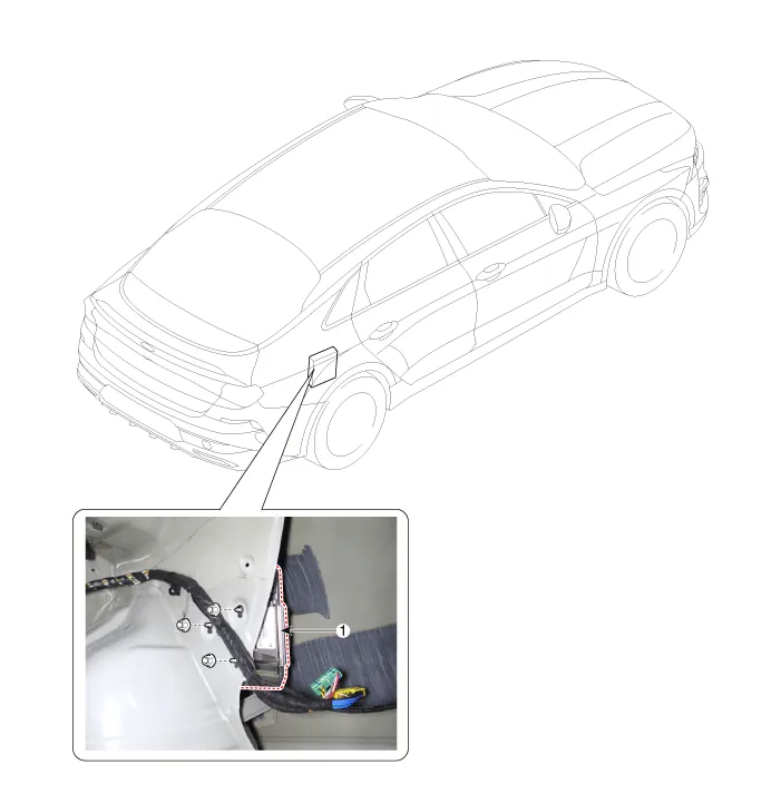
| 1. External amp |
Schematic diagrams
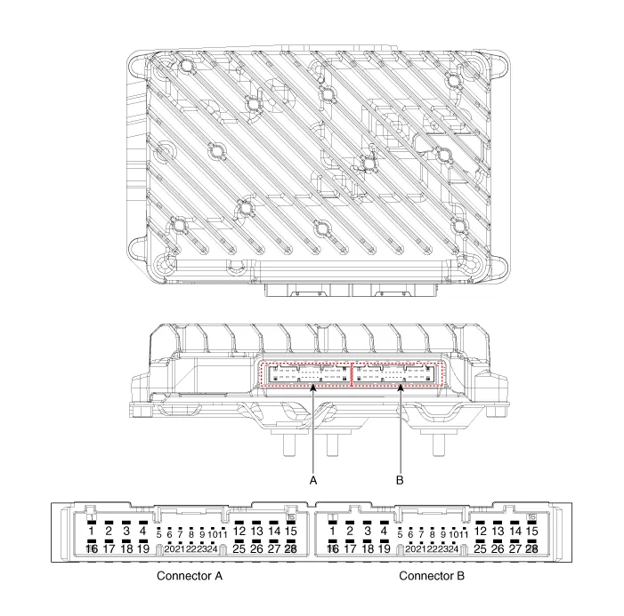
| Connector and Terminal Function |
|
Pin |
Function |
|
|
Connector A |
Connector B |
|
|
1 |
Battery (+) |
Right front door tweeter speaker (+) |
|
2 |
Battery (+) |
Left front door tweeter speaker (+) |
|
3 |
Battery (+) |
Sub woofer speaker (+) |
|
4 |
Battery (+) |
- |
|
5 |
- |
- |
|
6 |
MM-CAN (High) |
- |
|
7 |
MM-CAN (Low) |
Amplifier navigation voice (+) |
|
8 |
ACC |
- |
|
9 |
- |
- |
|
10 |
- |
- |
|
11 |
- |
- |
|
12 |
Right surround speaker (+) |
Right rear door speaker (+) |
|
13 |
Left surround speaker (+) |
Left rear door speaker (+) |
|
14 |
Right midrange speaker (+) |
Center speaker(+) |
|
15 |
Left midrange speaker (+) |
- |
|
16 |
Ground |
Right front door tweeter speaker (-) |
|
17 |
Ground |
Left front door tweeter speaker (-) |
|
18 |
Ground |
Sub woofer speaker (-) |
|
19 |
Ground |
- |
|
20 |
Amplifier SPDIF (High) |
- |
|
21 |
Amplifier SPDIF (Low) |
Amplifier navigation voice (-) |
|
22 |
Amplifier SPDIF (Ground) |
- |
|
23 |
- |
- |
|
24 |
IGN1 |
- |
|
25 |
Right surround speaker (-) |
Right rear door speaker (-) |
|
26 |
Left surround speaker (-) |
Left rear door speaker (-) |
|
27 |
Right midrange speaker (-) |
Center speaker (-) |
|
28 |
Left midrange speaker (-) |
- |
Repair procedures
| Inspection |
|

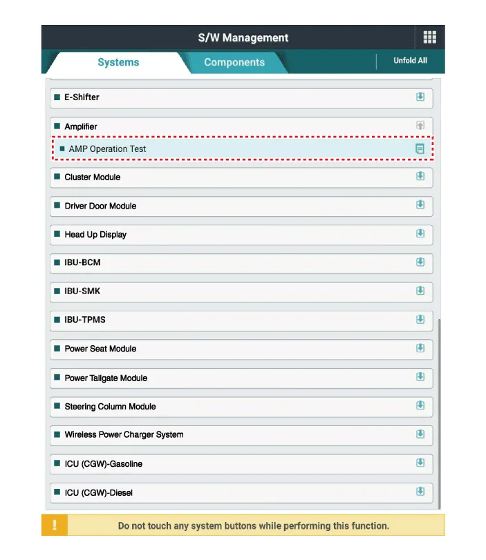
In the body electrical system, failure can be quickly diagnosed by using the vehicle diagnostic system (KDS).
|

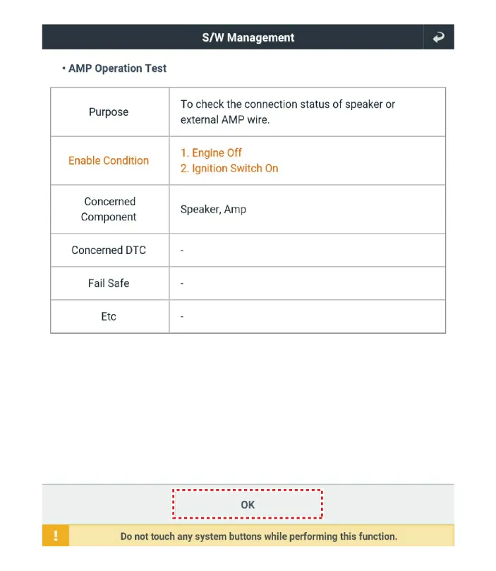
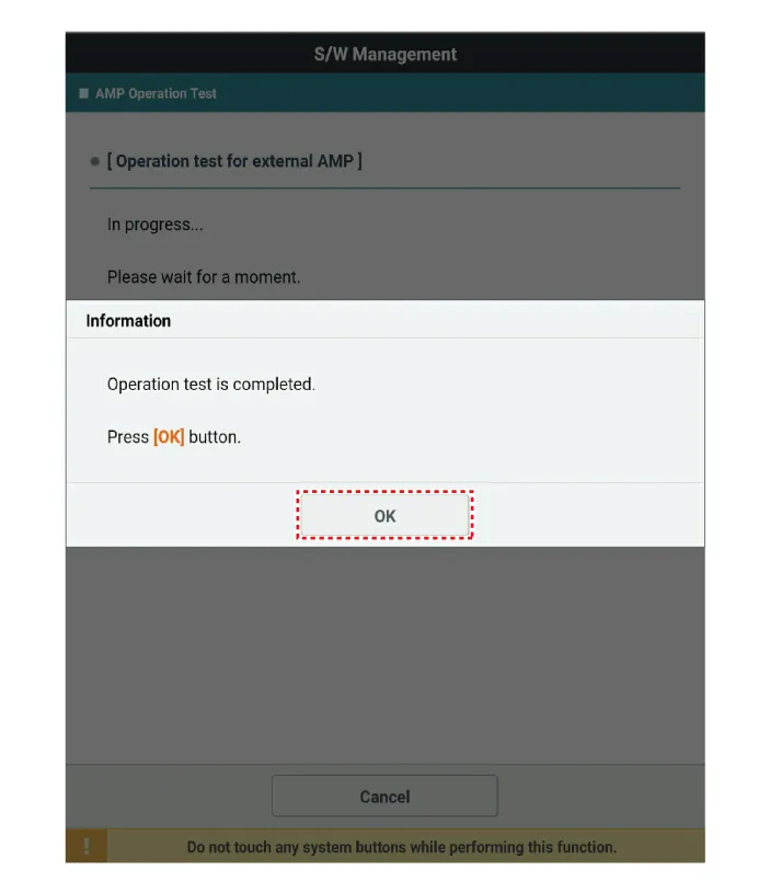
| 1. |
Perform the AMP operation test using the KDS.
|
| Removal |
| 1. |
Disconnect the negative battery terminal. |
| 2. |
Remove the right luggage side trim. (Refer to Body - "Luggage Side Trim") |
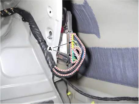
| 3. |
Disconnect the external amp connectors (A).
|
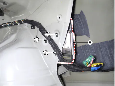
| 4. |
Remove the external amp (A) by loosening the mounting nuts.
|
| Installation |
| 1. |
Install in the reverse order of removal. |
Components and components location Components Location 1. Center speaker 2. Tweeter speaker 3. Front midrange speaker 4.
Components and components location Components Location 1. Audio/AVN head unit 2. Antenna feeder cable 3. Roof antenna Repair procedures Removal 1.
Other information:
Kia Optima DL3 2019-2026 Service and Repair Manual: Hazard Lamp Switch
Schematic diagrams Connector and Terminal Function Repair procedures Removal 1. Disconnect the negative battery terminal. 2. Remove the crash pad garnish [RH]. (Refer to Body - "Crash Pad Garnish") 3.
Kia Optima DL3 2019-2026 Service and Repair Manual: Panorama Sunroof Switch
Schematic diagrams Connector and Terminal Function Repair procedures Inspection 1. Remove the overhead console lamp. (Refer to Lighting System - "Overhead Console Lamp") 2. Check for continuity between the terminals in each switch position according to the table
Categories
- Manuals Home
- Kia Optima Owners Manual
- Kia Optima Service Manual
- Battery
- Motor Driven Power Steering
- Engine Mechanical System
- New on site
- Most important about car
