Kia Optima DL3: Audio/AVN System / Steering Wheel Remote Controller (SWRC)
Components and components location
| Components |
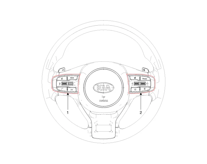
| 1. Left remote control switch
(Audio + Bluetooth + Voice) |
2. Right remote control switch
(Trip + SCC + LFA) |
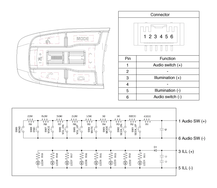
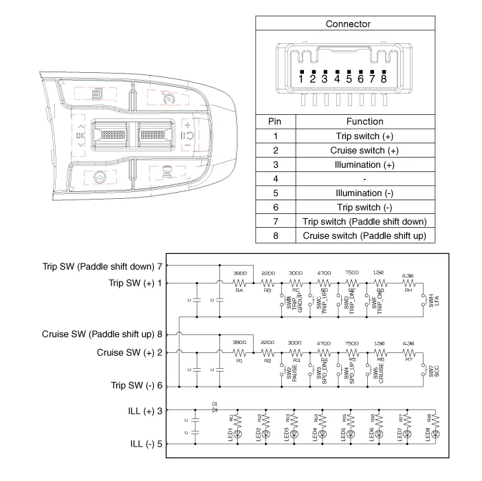
Schematic diagrams
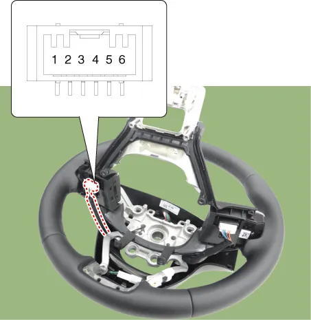
| Circuit Diagram |
| [Audio + Bluetooth + Voice] |
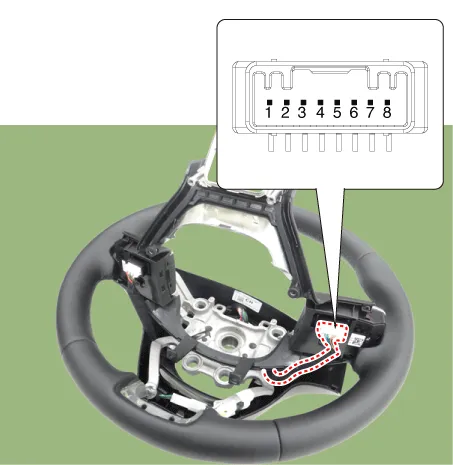
| [Trip + SCC + LFA] |
Repair procedures
| Removal |
| 1. |
Disconnect the negative battery terminal. |
| 2. |
Remove the steering wheel assembly. (Refer to Steering System - "Steering Wheel") |
| 3. |
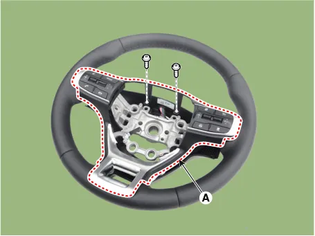
Loosen the mounting screws (A).
|
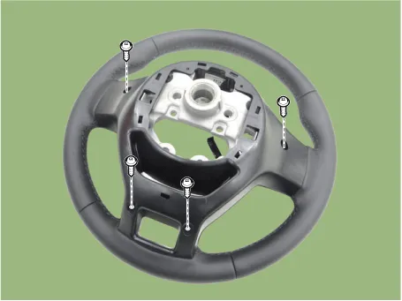
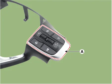
| 4. |
Remove the steering wheel remote controller assembly (A) by loosening the mounting screws.
|
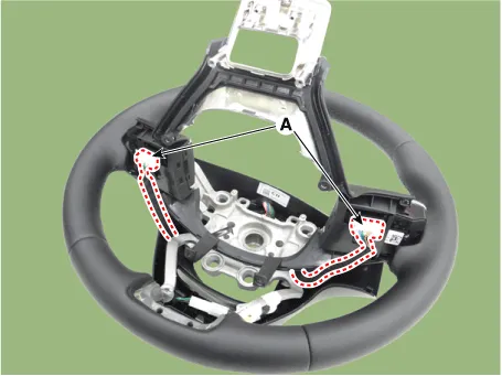
| 5. |
Disconnect the steering wheel remote controllers connectors (A).
|
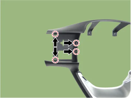
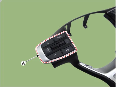
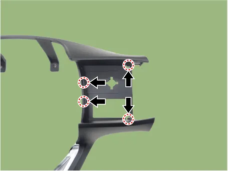
| 6. |
Remove the steering wheel remote controllers (A) by pushing the hooks in the direction of arrow. [LH]
[RH]
|
| Installation |
| 1. |
Install in the reverse order of removal. |
| Inspection |
| 1. |
Check for resistance between terminals in each switch position. [Audio + Bluetooth + Voice]
[Trip + SCC + LFA]
|
Components and components location Components Location 1. Audio/AVN head unit 2. Antenna feeder cable 3. Roof antenna Repair procedures Removal 1.
Schematic diagrams Circuit Diagram Audio Display Audio / AVN Repair procedures Removal 1.
Other information:
Kia Optima DL3 2019-2026 Service and Repair Manual: Trunk Room Lamp
Repair procedures Removal 1. Disconnect the negative battery terminal. 2. Remove the trunk room lamp (A) by pressing the hook. 3. Disconnect the trunk room lamp connector (A).
Kia Optima DL3 2019-2026 Service and Repair Manual: Overhead Console Lamp
Schematic diagrams Connector and Terminal Function [A Type] Connector A Pin E xcept Russia Region Russia only Function Function 1 Battery (+) Battery (+)
Categories
- Manuals Home
- Kia Optima Owners Manual
- Kia Optima Service Manual
- Front Axle Assembly
- Automatic Transaxle System
- Motor Driven Power Steering
- New on site
- Most important about car
