Kia Optima: Body Electrical System / Auto Lighting Control System
Kia Optima DL3 2019-2025 Service and Repair Manual / Body Electrical System / Auto Lighting Control System
Specifications
| Specifications |
|
Items |
Specifications |
|
|
Rated voltage |
DC +5 V |
|
|
Load |
Max. 1 mA (Relay load) |
|
|
Illuminations (Lux) |
100 |
0.76 ± 0.17 V |
|
200 |
1.30 ± 0.30 V |
|
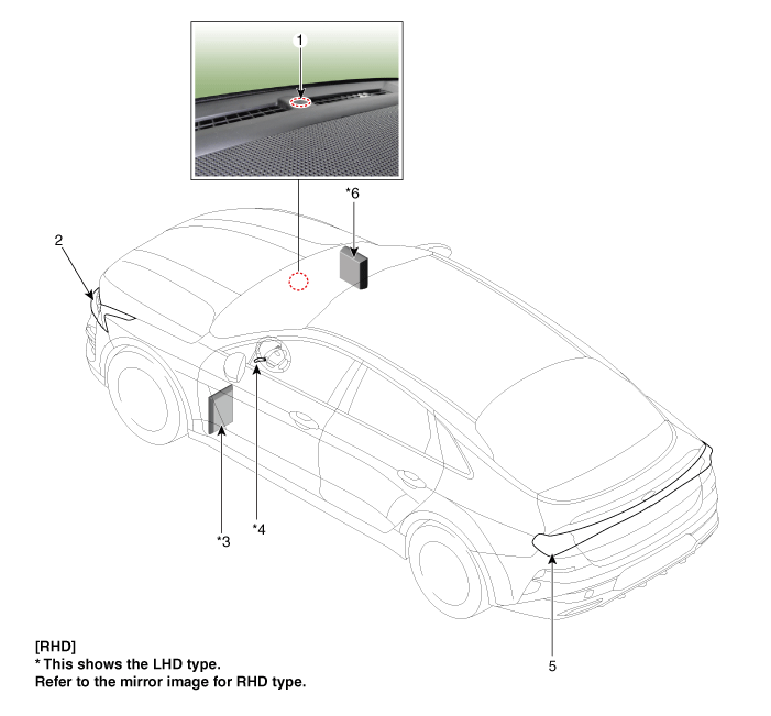
Components and components location
| Components |

| 1. Auto light sensor 2. Head lamps 3. Integrated central control unit (ICU) |
4. Multifunction switch 5. Rear combination lamp 6. Integrated body control unit (IBU) |
Description and operation
| Description |
| • |
This system uses an illumination sensor to automatically turn ON the tail lamp and head lamp based on the ambient light change in surrounding environment's. |
| • |
It activates when the vehicle enters/exits tunnel, or when the illumination condition in surrounding environment changes due to rain, snow, or fog. |
 Body Electrical System
General information
General Troubleshooting
Information
Before Troubleshooting
1.
Check applicable fuses in the appropriate fuse/relay box.
2.
...
 Auto Light Sensor
Schematic diagrams
Circuit Diagram
Repair procedures
Removal
1.
Disconnect the negative battery terminal.
2.
Remove the photo s ...
Other information:
Kia Optima DL3 2019-2025 Service and Repair Manual: A/V Navigation
Components and components location Components 1. AVN head unit Schematic diagrams Connector and Terminal Function AVN 5.0 [A Type] [B Type] Pin Function Connec ...
Kia Optima DL3 2019-2025 Service and Repair Manual: Photo Sensor
Description and operation Description The photo sensor is located at the center of the defrost nozzles. The photo sensor contains a photovoltaic (sensitive to sunlight) diode. The solar radiation received by its light receiving portion, generates an electromotive force in propor ...
Copyright © www.kioptima.com 2017-2025

