Kia Optima: Auto Lighting Control System / Auto Light Sensor
Kia Optima DL3 2019-2025 Service and Repair Manual / Body Electrical System / Auto Lighting Control System / Auto Light Sensor
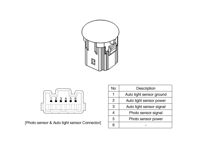
Schematic diagrams
| Circuit Diagram |

Repair procedures
| Removal |
| 1. |
Disconnect the negative battery terminal. |
| 2. |
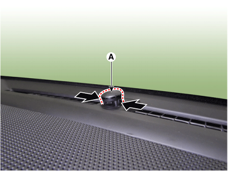
Remove the photo sensor & auto light sensor (A) by pressing the locking pins.
|
| 3. |
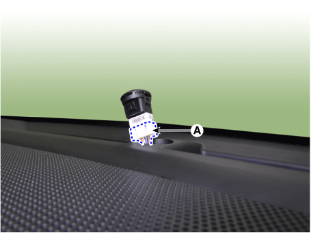
Disconnect the photo sensor & auto light sensor connector (A).
|
| Installation |
| 1. |
Install in the reverse order of removal. |
 Auto Lighting Control System
Specifications
Specifications
Items
Specifications
Rated voltage
DC +5 V
Load
Max. 1 mA (Relay load) ...
 Audio/AVN System
Components and components location
Component Location
1. Audio head unit/AVN head unit
2. Tweeter speaker
3. Center speaker
4. Front midrange speaker
5. F ...
Other information:
Kia Optima DL3 2019-2025 Service and Repair Manual: Front Seat Inner Shield Cover
Components and components location Component Location 1. Front seat inner shield cover Repair procedures Replacement • When removing with a ...
Kia Optima DL3 2019-2025 Service and Repair Manual: Shift Lever
Components and components location Component 1. Shift Lever Assembly 2. Shift Cable Assembly Repair procedures Removal 1. Shift the gear to "N". 2. Remove the floor console assembly. ...
Copyright © www.kioptima.com 2017-2025


