Kia Optima DL3: Restraint
General information
| General |
The supplemental restraint system (SRS) is designed to supplement the seat belt to help reduce the risk or severity of injury to the driver and passenger by activating and deploying the driver, passenger, side airbag and seat belt pretensioner in certain frontal or side collisions.
The SRS (Airbag) consists of: a driver side airbag module with the folded cushion and an inflator unit located at the center of the steering wheel, a passenger side airbag module with the folded cushion assembled with inflator unit located in the passenger side crash pad, side airbag modules with the folded cushion and an inflator unit located in the front seat, and curtain airbag modules with folded cushions and inflator units located inside the headliner. The impact sensing function of the SRSCM is carried out by electronic accelerometer that continuously measures the vehicle’s acceleration and delivers the corresponding signal through amplifying and filtering circuitry to the microprocessor.
SRSCM (SRS Control Module)
SRSCM will detect front impact with front impact sensor, and side impact with side impact sensor, to determine airbag module deployment.
| 1. |
DC/DC converter: DC/DC converter in power supply unit includes up/down transformer converter, and provides ignition voltage to 2 front airbag ignition circuits and the internal operation voltage to the SRSCM. If the internal operation voltage is below critical value setting, it will perform resetting. |
| 2. |
Back up power supply: SRSCM has separate back up power supply, that will supply deployment energy instantly in low voltage condition or upon power failure by front crash. |
| 3. |
Self diagnosis: SRSCM will constantly monitor current SRS operation status and detect system failure while vehicle power supply is on. System failure may be checked with trouble codes using KDS. |
| 4. |
Airbag warning lamp on: Upon detecting error, the module will transmit signal to SRSCM indicator lamp located in cluster. MIL lamp will inform the driver of SRS error. Upon Ignition on, SRS lamp will turn on for about six seconds. |
| 5. |
Trouble code registration: Upon error occurrence in system, SRSCM will store DTC corresponding to the error. DTC can be cleared only by KDS. However, if an internal fault code is logged or if a crash is recorded, the fault code(s) cannot be cleared. |
| 6. |
Self diagnostic connector: Data stored in SRSCM memory will be sent to KDS or other external output devices through connector located below the driver side crash pad. |
| 7. |
Once airbag is deployed, the SRSCM must be replaced. It should never be reused. |
| 8. |
Side airbag deployment will be determined by SRSCM that detects satellite sensor impact signal upon a side crash. |
| 9. |
Check for the normal operation of SRSCM after repair procedure. |
Tightening torque
| Tightening Torques |
|
Item |
N·m |
kgf·m |
lb·ft |
lb·in |
|
Passenger airbag (PAB) bolt |
3.9 - 5.8 |
0.4 - 0.6 |
2.8 - 4.3 |
34.7 - 52.0 |
|
Side airbag (SAB) nut |
5.8 - 7.8 |
0.6 - 0.8 |
4.3 - 5.7 |
52.0 - 69.4 |
|
Curtain airbag (CAB) bolt |
7.8 - 11.7 |
0.8 - 1.2 |
5.7 - 8.6 |
- |
|
Curtain airbag (CAB) nut |
3.9 - 5.8 |
0.4 - 0.6 |
2.8 - 4.3 |
34.7 - 52.0 |
|
SRS control module (SRSCM) bolt |
10.8 - 13.7 |
1.1 - 1.4 |
8.0 - 10.1 |
- |
|
SRS control module (SRSCM) nus |
6.9 - 7.8 |
0.7 - 0.8 |
5.1 - 5.7 |
60.8 - 69.4 |
|
Front impact sensor (FIS) bolt |
8.8 - 10.8 |
0.9 - 1.0 |
6.5 - 7.2 |
|
|
Gravity side impact sensor (P-SIS) |
2.0 - 2.9 |
0.2 - 0.3 |
1.4 - 2.2 |
17.4 - 26.0 |
|
Gravity side impact sensor (G-SIS) |
6.9 - 7.8 |
0.7 - 0.8 |
5.1 - 5.7 |
60.8 - 69.4 |
|
Seat belt retractor & Pretensioner |
39.2 - 53.9 |
4.0 - 5.5 |
28.9 - 39.8 |
- |
Special service tools
| Special Service Tools |
|
Tool Name / Number |
Illustration |
Description |
|
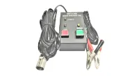
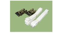
Deployment tool 0957A-34100A |
|
Used for deploying airbag |
|
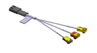
Deployment adapter 0K57A-3U100A |
|
Used with the deployment tool (0957A-34100A) when deploying DAB, PAB, CAB,
BPT |
|
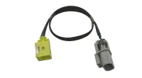
Deployment adapter 0957A-2W100 |
|
Used with the deployment tool (0957A-34100A) when deploying SAB |
|
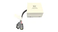
Dummy 0957A-38200 |
|
Simulator to check the resistance of airbag wiring harness |
|
Dummy adapter 0957A-2W200 |
|
Used with the dummy (0957A-38200) when checking the resistance of SAB |
|
Dummy adapter 0957A-2G000 |
|
Used with the dummy (0957A-38200) when checking the resistance of DAB, PAB, CAB, BPT |
DAB : Driver Airbag
PAB : Passenger Airbag
SAB : Side Airbag
CAB : Curtain Airbag
BPT : Seat Belt Pretensioner
General safety information and caution
| Precautions |
| General Precautions |
Please read the following precautions carefully before performing the airbag system service.
Observe the instructions described in this manual, or the airbags could accidentally deploy and cause damage or injuries.
| • |
Except when performing electrical inspections, always turn the ignition switch OFF and disconnect the negative cable from the battery, and wait at least three minutes before beginning work. |
The contents in the memory are not erased even if the ignition switch is turned OFF or the battery cables are disconnected from the battery. |

| • |
Use the replacement parts which are manufactured to the same standards as the original parts and quality. Do not install used SRS parts from another vehicle. Use only new parts when making SRS repairs. |
| • |
Carefully inspect any SRS part before you install it. Do not install any part that shows signs of being dropped or improperly handled, such as dents, cracks or deformation.
|
| • |
Before removing any of the SRSCM parts (including the disconnection of the connectors), always disconnect the SRSCM connector. |
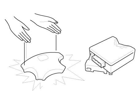
Airbag Handling and Storage
Do not disassemble the airbags; it has no serviceable parts. Once an airbag has been deployed, it cannot be repaired or reused.
For temporary storage of the air bag during service, please observe the following precautions.
| • |
Store the removed airbag with the pad surface up. |
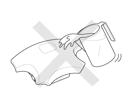
| • |
Keep free from any oil, grease, detergent, or water to prevent damage to the airbag assembly.
|
| • |
Store the removed airbag on secure, flat surface away from any high heat source (exceeding 85 C/185 F). |
| • |
Never perform electrical inspections to the airbags, such as measuring resistance. |
| • |
Do not position yourself in front of the airbag assembly during removal, inspection, or replacement. |
| • |
Refer to the scrapping procedures for disposal of the damaged airbag. |
| • |
Be careful not to bump or impact the SRS unit or the side impact sensors or front impact sensors whenever the ignition switch is ON, wait at least three minutes after the ignition switch is turned OFF before begin work. |
| • |
During installation or replacement, be careful not to bump (by impact wrench, hammer, etc.) the area around the SRS unit and the side impact sensor and the front impact sensors. The airbags could accidentally deploy and cause damage or injury. |
| • |
Replace the front airbag module, SRSCM, FIS when deploying the front airbag. Replace the airbag wiring when the airbag wiring get damaged. Replace the side airbag module, the curtain airbag module, SRSCM, SIS when deploying the side airbag. Replace the airbag when the airbag wiring get damaged. |
| • |
After a collision in which the airbags or the side air bags did not deploy, inspect for any damage or any deformation on the SRS unit and the side impact sensors. If there is any damage, replace the SRS unit, the front impact sensor and/or the side impact sensors. |
| • |
Do not disassemble the SRS unit, the front impact sensor or the side impact sensors. |
| • |
Turn the ignition switch OFF, disconnect the battery negative cable and wait at least three minutes before beginning installation or replacement of the SRS unit. |
| • |
Be sure the SRS unit, the front impact sensor and side impact sensors are installed securely with the mounting bolts. |
| • |
Do not spill water or oil on the SRS unit, or the front impact sensor or the side impact sensors and keep them away from dust. |
| • |
Store the SRS unit, the front impact sensor and the side impact sensors in a cool (15 ~ 25 C/ 59 ~ 77 F) and dry (30 ~ 80% relative humidity, no moisture) area. |
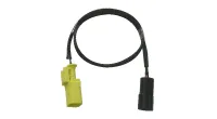
Wiring Precautions
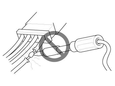
SRS wiring can be identified by special yellow outer covering. Observe the instructions described in this section.
| • |
Never attempt to modify, splice, or repair SRS wiring. If there is an open or damage in SRS wiring, replace the harness.
|
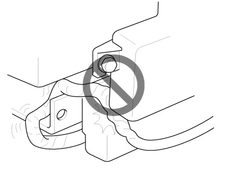
| • |
Be sure to install the harness wires so that they are not pinched, or interfere with other parts.
|
| • |
Make sure all SRS ground locations are clean, and grounds are securely fastened for optimum metal-to-metal contact. Poor grounding can cause intermittent problems that are difficult to diagnose. |
Precautions for Electrical Inspections
| • |
When using electrical test equipment, insert the probe of the tester into the wire side of the connector. Do not insert the probe of the tester into the terminal side of the connector, and do not tamper with the connector.
|
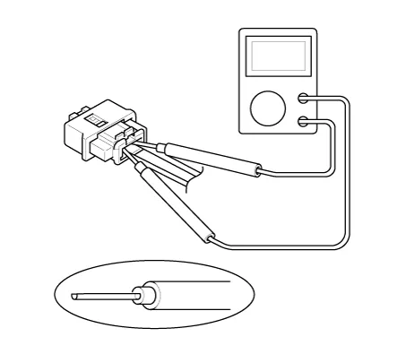
| • |
Use a u-shaped probe. Do not insert the probe forcibly. |
| • |
Use specified service connectors for troubleshooting. Using improper tools could cause an error in inspection due to poor metal contact. |
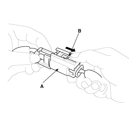
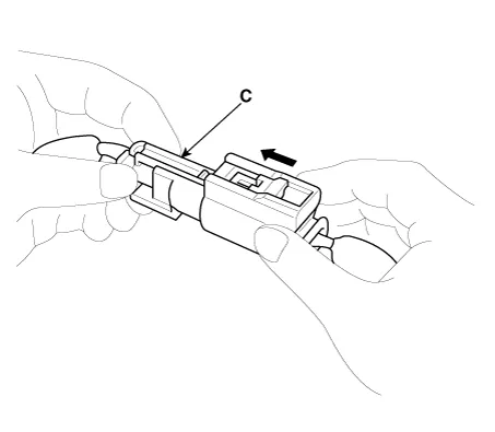
Spring-Loaded Lock Connector
Some SRS system connectors have a spring-loaded lock.
Airbag Connector
| Disconnecting |
To release the lock, pull the spring-loaded sleeve (A) and the slider (B), while holding the opposite half of the connector.
Pull the connector halves apart. Be sure to pull on the sleeve and not on the connector half.
| Connecting |
Hold both connector halves and press firmly until the projection(C) of the sleeve-side connector clicks to lock.
The airbag module disposal procedure
| The Airbag Module Disposal Procedure |
| • |
When disposing a vehicle that is equipped with an airbag system and other restraint devices such as seatbelt pretensioners, airbags must first be deployed. |
| • |
Airbag deployment must be performed by an experienced technician. |
| • |
Airbags that have been deployed cannot be reused and must not be mounted to any other vehicles. |
|

Tools and equipment required to dispose of the airbag module
|
Illustration |
Tool Name |
Remarks |
|
|
Gloves |
|
|
|
Goggles |
|
|
|
Earplugs |
|
|
|
2 tires with wheel rim |
(Top / Bottom) |
|
|
3 tires without wheel rim |
(Middle) |
|
|
Rope Strap / Ratchet Strap |
(Use for connecting the airbag module equipment and tires according to the
deployment instructions) |
|
|
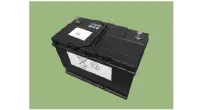
12V battery |
|


Deployed within the vehicle
| 1. |
Turn the ignition switch OFF and disconnect the negative battery terminal.
|
| 2. |
Confirm that each airbag module is securely mounted. |
| 3. |
Refer to the following to prepare for the deployment of the airbag system:
|
| 4. |
The mechanic shall be located at least 7 meters away from the vehicle. |
| 5. |
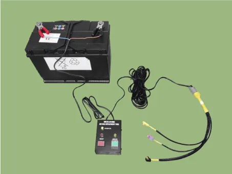
Connect the external battery after connecting the deployment tool (0957A-34100A) from the deployment adaptor.
|
| 6. |
Activate the switch of the airbag deployment tool to deploy the airbag system.
|

| 7. |
Place deployed airbags in a sturdy plastic bag, securely seal the bag, and dispose of the bag.
|

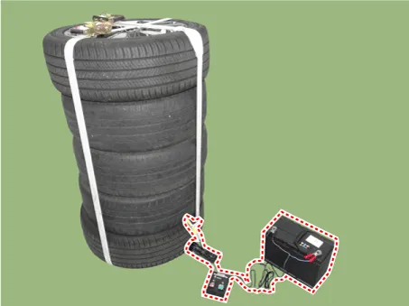
Deployment in a vehicle outside
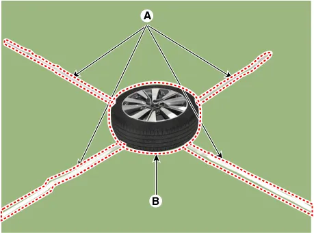
| 1. |
Lay the rope (A) on the floor to form a cross and place the wheeled tire (B) over it.
|
| 2. |
Install the deployment adaptor (0K57A-3U100A) from airbag module/pretensioner.
|
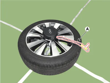
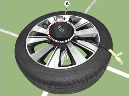
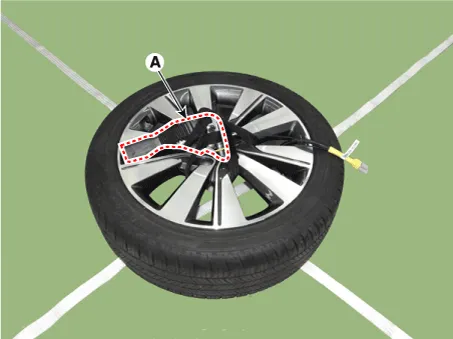
| 3. |
Fix the airbag module/pretensioner (A) from wheel. [Airbag Module]
[Pretensioner]
|
| 4. |
Place three waste tires (A) first, then place wheeled tire (B) on top of the pile. |
| 5. |
Secure the tire with the ratchet strap (C).
|

| 6. |
Connect to the battery. Connect the airbag deployment tool (0957A-34100A) to the deployment adapter (0K57A-3U100A).
|
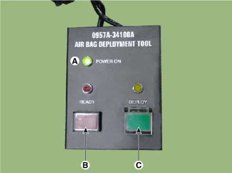
| 7. |
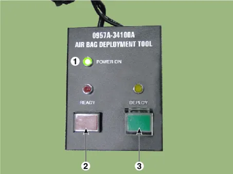
When the POWER ON (A) is illuminated on the airbag deployment tool, press READY (B), and then DEPLOY (C) to deploy the airbag.
|
| 8. |
Place deployed airbags in a sturdy plastic bag, securely seal the bag, and dispose of the bag.
|
- SRSCM
- Airbag Module
- Driver Airbag (DAB) Module and Clock Spring
- Passenger Airbag (PAB) Module
- Side Airbag (SAB) Module
- Curtain Airbag (CAB) Module
- Seat Belt Pretensioner (BPT)
Components and components location Components 1. Steering gear box 2. STie rod end 3. Dust cap Repair procedures Removal 1.
Components and components location Components 1. Supplemental Restraint System Control Module (SRSCM) 2. Gravity Side Impact Sensor (G-SIS) 3.
Other information:
Kia Optima DL3 2019-2026 Service and Repair Manual: Integrated Memory Seat (IMS) Unit
Specifications Specifications Item Specifications Rated voltage DC 12 V Operating voltage DC 9 - 16 V Operating temperature range -22 to 167°F (-30 to 75°C) Dark current Max.
Kia Optima DL3 2019-2026 Service and Repair Manual: Washer Switch
R
Categories
- Manuals Home
- Kia Optima Owners Manual
- Kia Optima Service Manual
- Cooling System
- Body (Interior and Exterior)
- Motor Driven Power Steering
- New on site
- Most important about car
