Kia Optima DL3: Cylinder Head Assembly / Cylinder Head Cover
Components and components location
| Components |
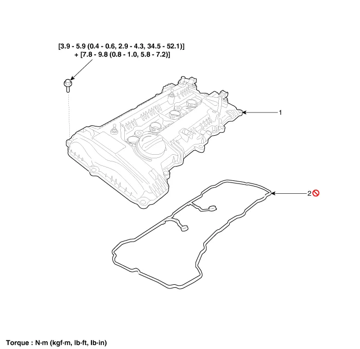
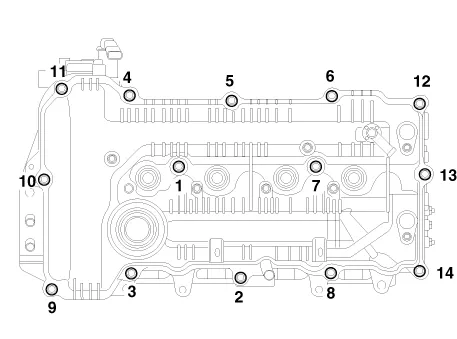
| 1. Cylinder head cover |
2. Cylinder head cover gasket
|
Repair procedures
| Removal |
|

Mark all wiring and hoses to avoid misconnection. |

| 1. |
Remove the engine cover. (Refer to Engine and Transaxle Assembly - "Engine Cover") |
| 2. |
Disconnect the battery negative terminal. |
| 3. |
Disconnect the wiring connectors and harness clamps and remove the connector brackets around the cylinder head cover.
|
| 4. |
Remove the air cleaner assembly. (Refer to Intake and Exhaust System - "Air Cleaner") |
| 5. |
Remove the ignition coils. (Refer to Engine Electrical System - “Ignition Coil”) |
| 6. |
Remove the engine oil level gauge. (Refer to Lubrication System - “Oil Level Gauge & Pipe”) |
| 7. |
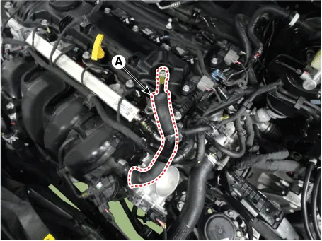
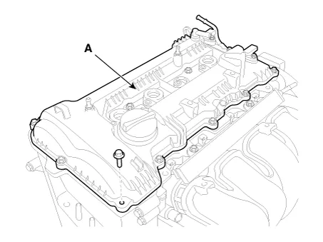
Disconnect the positive crankcase ventilation (PCV) hose (A).
|
| 8. |
Remove the cylinder head cover (A).
|

| Installation |
| 1. |
Install cylinder head cover.
|
| 2. |
Install the other parts reverse order of removal. |
Components and components location Components 1. Camshaft bearing cap 2. Camshaft front bearing cap 3. Exhaust camshaft 4.
Components and components location Components 1. Camshaft bearing cap 2. Camshaft front bearing cap 3. Exhaust camshaft 4.
Other information:
Kia Optima DL3 2019-2026 Service and Repair Manual: Power Door Lock Module
Repair procedures Inspection When prying with a flat-tip screwdriver or use a prying trim tool, wrap it with protective tape, and apply protective tape around the related parts, to prevent damage.
Kia Optima DL3 2019-2026 Service and Repair Manual: Temperature Control Actuator
Components and components location Components Location 1. Temperature control actuator [LH] 2. Temperature control actuator [RH] Description and operation Description The temperature control actuator is located at the heater unit.
Categories
- Manuals Home
- Kia Optima Owners Manual
- Kia Optima Service Manual
- Cooling System
- Brake System
- Floor Console Assembly
- New on site
- Most important about car
