Kia Optima DL3: Heater / Evaporator Core
Repair procedures
| Replacement |
| 1. |
Disconnect the negative (-) battery terminal. |
| 2. |
Remove the heater and blower assembly. (Refer to Heater - "Heater Unit") |
| 3. |
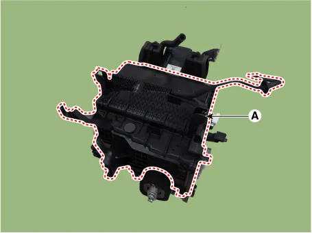
Loosen the mounting screws, lock pin and remove the evaporator core cover (A).
|
| 4. |
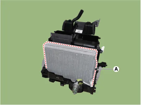
Remove the evaporator cover (A) from heater unit.
|

| 5. |
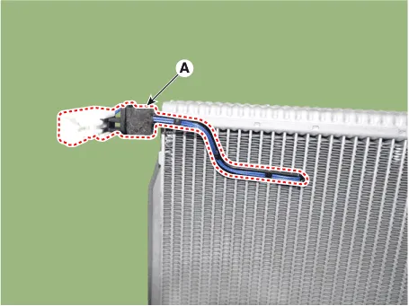
Separate the evaporator temperature sensor (A) from the evaporator core.
|
| 6. |
To install, reverse the removal procedure. |
Repair procedures Replacement 1. Disconnect the negative (-) battery terminal. 2. Remove the heater and blower assembly.
Components and components location Components Location 1. Temperature control actuator [LH] 2. Temperature control actuator [RH] Description and operation Description The temperature control actuator is located at the heater unit.
Other information:
Kia Optima DL3 2019-2026 Service and Repair Manual: Room Lamp
Repair procedures Removal When removing with a flat-tip screwdriver or remover, wrap protective tape around the tools to prevent damage to components. 1.
Kia Optima DL3 2019-2026 Service and Repair Manual: Smart Key Antenna
Repair procedures Removal Interior Antenna 1 1. Disconnect the negative battery terminal. 2. Remove the surround view monitor (SVM) unit. (Refer to Advanced Driver Assistance System (ADAS) - "Surround View Monitor (SVM) Unit") 3.
Categories
- Manuals Home
- Kia Optima Owners Manual
- Kia Optima Service Manual
- Motor Driven Power Steering
- Body Electrical System
- Body (Interior and Exterior)
- New on site
- Most important about car
