Kia Optima DL3: Smart Key System / Smart Key Antenna
Repair procedures
| Removal |
Interior Antenna 1
| 1. |
Disconnect the negative battery terminal. |
| 2. |
Remove the surround view monitor (SVM) unit. (Refer to Advanced Driver Assistance System (ADAS) - "Surround View Monitor (SVM) Unit") |
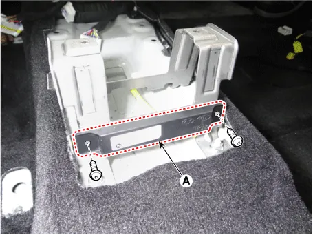
| 3. |
Remove the SVM bracket (A) by loosening the mounting nuts.
|
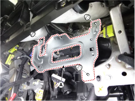
| 4. |
Remove the fixing clip (A) from the SVM bracket.
|
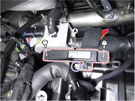
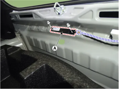
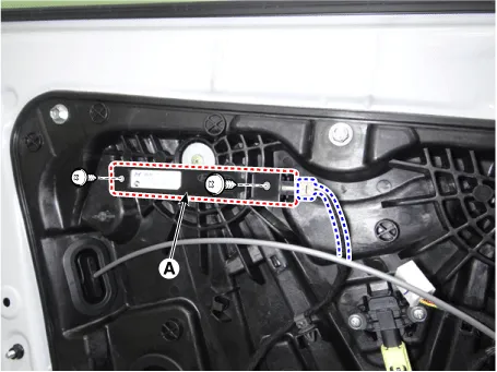
| 5. |
Remove the interior antenna 1 (A) by loosening the screws after disconnecting the connector.
|
Interior Antenna 2
| 1. |
Disconnect the negative battery terminal. |
| 2. |
Remove the floor console assembly. (Refer to Body - "Floor Console Assembly") |
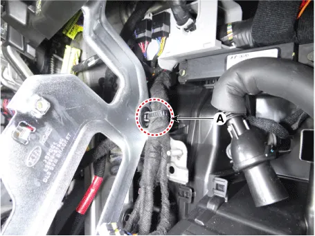
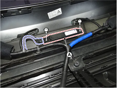
| 3. |
Disconnect the interior antenna 2 connector (A).
|
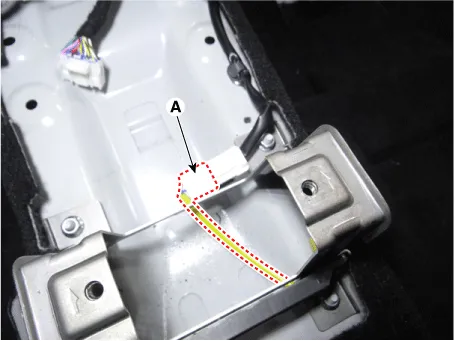
| 4. |
Remove the interior antenna 2 (A) by loosening the mounting screws.
|
Interior Antenna 3
| 1. |
Disconnect the negative battery terminal. |
| 2. |
Remove the rear transverse trim. (Refer to Body - "Rear Transverse Trim") |
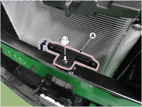
| 3. |
Remove the interior antenna 3 (A) by loosening the nuts after disconnecting the connector.
|
Exterior Bumper Antenna
| 1. |
Disconnect the negative battery terminal. |
| 2. |
Remove the rear bumper assembly. (Refer to Body - "Rear Bumper Assembly") |
| 3. |
Remove the exterior bumper antenna (A) by loosening the screws after disconnecting the connector.
|
Front Antenna
| 1. |
Disconnect the negative battery terminal. |
| 2. |
Remove the front bumper assembly. (Refer to Body - "Front Bumper Assembly") |
| 3. |
Remove the front antenna (A) by loosening the nut after disconnecting the connector.
|
Front Door Antenna
| 1. |
Disconnect the negative battery terminal. |
| 2. |
Remove the front door trim. (Refer to Body - "Front Door Trim") |
| 3. |
Remove the front door antenna (A) by loosening the screws after disconnecting the connector.
|
| Installation |
| 1. |
Install in the reverse of the removal. |
| Inspection |
| 1. |
Inspect the antenna by using the KDS. (Refer to Smart Key System - "Smart Key Diagnostic") |
Schematic diagrams Connector and Terminal Function Pin Function Connector A Connector B Connector C Connector D 1 - Front washer switch (Output) - Driver outside handle switch (Input) 2 Rear seat belt indicator_Left (Output) - ESCL Enable (Output) Assist outside handle switch (Input) 3 - - ESCL - (Output) - 4 - - - - 5 External buzzer (Output) - - RPM (Input) 6 Rear seat belt indicator_Center (Output) Wiper parking switch (Input) - SSB symbol illumination (+) (Output) 7 Puddle pocket lamp (Output) - ESCL Unlock switch (Input) ACC relay (Output) 8 Rear seat belt indicator_Right (Output) Brake switch (Input) - IGN1 relay (Output) 9 - - - IGN2 relay (Output) 10 Headlamp high switch (Input) Front wiper volume switch (Input) ESCL + (Output) Starter relay (Output) 11 - - Assist outside handle antenna (+) (Output) 12 - LIN4 (Safety ECU) Interior antenna 2 (+) (Output) 13 Rear view switch (Input) PAS Option (Input) Trunk interior antenna 3 (+) (Output) 14 - - Interior antenna 1 (+) (Output) 15 RPAS Power (Output) B-CAN (Low) Bumper antenna (+) (Output) 16 FRAS Power (Output) B-CAN (High) Driver outside handle antenna (+) (Output) 17 PAS/RPAS Power (Input) - - 18 - Ground (Power) - 19 - - - 20 Ground (ECU) Immobilizer power (Output) - 21 - Immobilizer ground (Output) SSB switch 1 (Input) 22 K-Line_Immobilizer - SSB switch 2 (Input) 23 - PAS/RPAS Switch indicator (Output) Clutch IGN lock switch 24 - Front wiper switch (Input) ESCL COM 25 Sunroof status (Input) - Wheel speed sensor (Input) 26 PAS/RPAS Switch (Input) Multifunction switch ground (Input) - 27 ATM Solenoid (Output) Wiper power relay (Output) - 28 LIN3 (Rain sensor) Auto light sensor ground (Output) - 29 LIN2 (ROA) Auto light sensor signal (Input) - 30 LIN1 (PDW-F or PDW-R) Auto light sensor power (Output) Start feed back (Input) 31 Door unlock signal (For IFU) EMS (Output) - Assist outside handle antenna (-) (Output) 32 Light switch (Input) Front wiper high relay (Output) Interior antenna 2 (-) (Output) 33 Fog switch (Input) Front wiper low relay (Output) Trunk interior antenna 3 (-) (Output) 34 IGN2 (Input) Front wiper low backup switch (Input) Interior antenna 1 (-) (Output) 35 IGN1 (Input) P-CAN (Low) Bumper antenna (-) (Output) 36 ACC (Input) P-CAN (High) Driver outside handle antenna (-) (Output) 37 Battery + (ECU) - 38 Battery + (Power) - 39 - - 40 Front heated nozzle (Output) 'P' Position (input) Repair procedures Removal Integrated Body control Unit (IBU) 1.
Repair procedures Inspection 1. In the body electrical system, failure can be quickly diagnosed by using the vehicle diagnostic system (KDS).
Other information:
Kia Optima DL3 2019-2026 Service and Repair Manual: Vanity Lamp
Repair procedures Removal When removing with a flat-tip screwdriver or remover, wrap protective tape around the tools to prevent damage to components. 1.
Kia Optima DL3 2019-2026 Service and Repair Manual: Heater Control Unit
Components and components location Components Connector Pin Function [Connector A] Pin NO Funtion Pin NO Funtion 1 Ground 11 Ground 2 Clean signal 12 -
Categories
- Manuals Home
- Kia Optima Owners Manual
- Kia Optima Service Manual
- Engine Control / Fuel System
- Automatic Transaxle System
- Battery
- New on site
- Most important about car
