Kia Optima DL3: Integrated Memory Seat (IMS) / Integrated Memory Seat (IMS) Unit
Specifications
| Specifications |
|
Item |
Specifications |
|
Rated voltage |
DC 12 V |
|
Operating voltage |
DC 9 - 16 V |
|
Operating temperature range |
-22 to 167°F (-30 to 75°C) |
|
Dark current |
Max. 1.2 mA |
Components and components location
| Component Location |
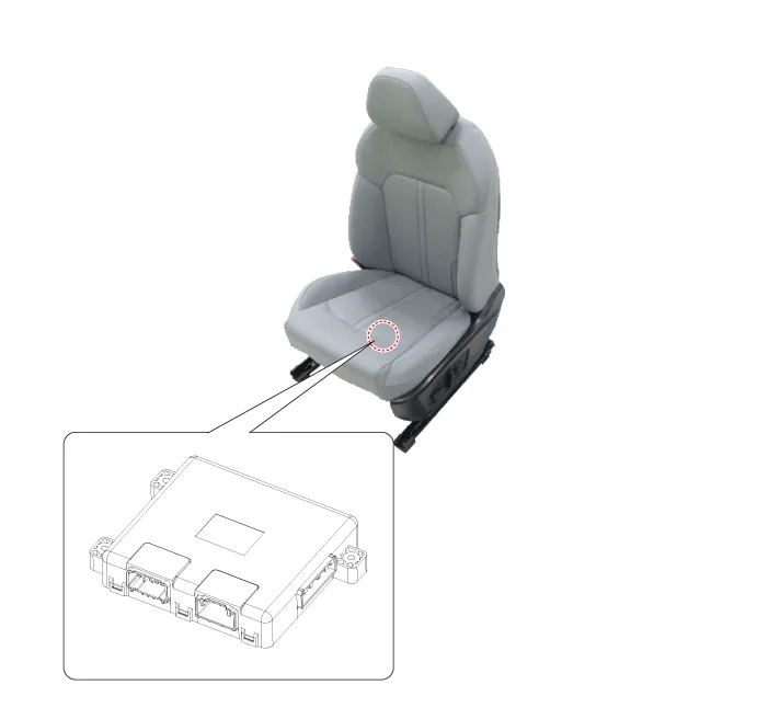
| 1. Integrated memory seat (IMS)
unit |
Schematic diagrams
| Connector and Terminal Function |
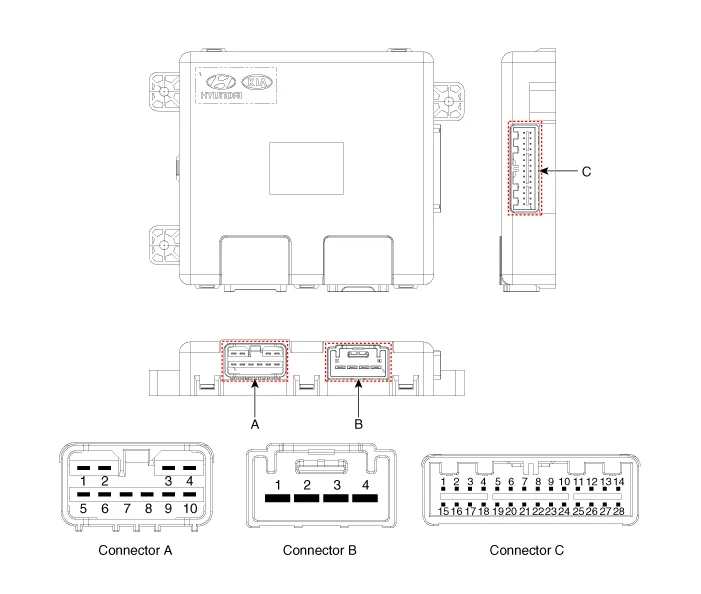
|
Pin |
Function |
||
|
Connector A |
Connector B |
Connector C |
|
|
1 |
- |
Battery (+) |
Slide switch signal (Forward) |
|
2 |
Recline motor (Forward) |
Battery (+) |
Recline switch signal (Forward) |
|
3 |
Rear height motor (Up) |
Ground |
Front tilt switch signal (Up) |
|
4 |
Slide motor (Forward) |
Ground |
Rear height switch signal (Up) |
|
5 |
- |
|
- |
|
6 |
Recline motor (Backward) |
B-CAN (High) |
|
|
7 |
Front tilt motor (Up) |
B-CAN (Low) |
|
|
8 |
Front tilt motor (Down) |
- |
|
|
9 |
Rear height motor (Down) |
Driver lumbar support motor (Mid) |
|
|
10 |
Slide motor (Backward) |
Slide sensor |
|
|
11 |
|
- |
|
|
12 |
- |
||
|
13 |
Seat position sensor power |
||
|
14 |
IGN1 |
||
|
15 |
Slide switch signal (Backward) |
||
|
16 |
Recline switch signal (Backward) |
||
|
17 |
Front tilt switch signal (Down) |
||
|
18 |
Rear height switch signal (Down) |
||
|
19 |
- |
||
|
20 |
Ground |
||
|
21 |
- |
||
|
22 |
- |
||
|
23 |
Driver lumbar support motor (Def) |
||
|
24 |
- |
||
|
25 |
- |
||
|
26 |
- |
||
|
27 |
- |
||
|
28 |
Battery (+) |
||
Repair procedures
| Removal |
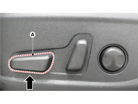
Before removing the driver side seat assembly, pull it upward to the maximum by pushing the front seat height adjusting switch (A).
|
| 1. |
Disconnect the negative battery terminal. |
| 2. |
Remove the front drive seat assembly. (Refer to Body - "Front Seat Assembly") |
| 3. |
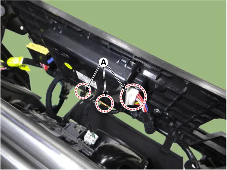
Disconnect the IMS unit connectors (A).
|
| 4. |
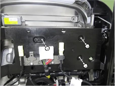
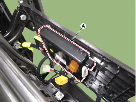
Remove the IMS unit (A) by loosening the mounting screws.
|
| Installation |
| 1. |
Install in the reverse order of removal. |
| Inspection |
| 1. |
In the body electrical system, failure can be quickly diagnosed by using the vehicle diagnostic system (KDS). The diagnostic system (KDS) provides the following information.
|
| 2. |
Select the 'Car model' and the 'Power Seat Module (PSM)' to be checked in order to check the vehicle with the tester. |
| 3. |
Select the 'Current Data' menu to search the current state of the input/output data. The input/output data for the sensors corresponding to the power seat module (PSM) can be checked. |
| 4. |
To forcibly actuate the input value of the module to be checked, select option 'Actuation Test'. |
Schematic diagrams Connector and Terminal Function Repair procedures Removal When prying with a flat-tip screwdriver or use a prying trim tool, wrap it with protective tape, and apply protective tape around the related parts, to prevent damage.
Other information:
Kia Optima DL3 2019-2026 Service and Repair Manual: Power Door Locks
C
Kia Optima DL3 2019-2026 Service and Repair Manual: Smart Key
Repair procedures Adjustment Smart Key Code Saving 1. Connect the VCI II in driver side crash pad lower panel, turn the power on KDS. 2. Select the vehicle model and then do "Smart key code saving".
Categories
- Manuals Home
- Kia Optima Owners Manual
- Kia Optima Service Manual
- Brake System
- Suspension System
- Steering System
- New on site
- Most important about car


