Kia Optima DL3: Brake System / Front Brake Disc
Components and components location
| Components |

| 1. Front Brake Caliper 2. Front Brake Disc |
3. Front Axle |
Repair procedures
| Removal |
| 1. |
Disconnect the (-) battery terminal. |
| 2. |
Remove the front wheel and tire. (Refer to Suspension System - "Wheel") |
| 3. |
Loosen the guide rod bolt and then pivot the caliper body (A) up out of the way.
|

| 4. |
Remove the brake pad (A).
|

| 5. |
Remove the pad retainer (A).
|
| 6. |
Remove the caliper carrier (A) by loosening the caliper mouniting bolts.
|


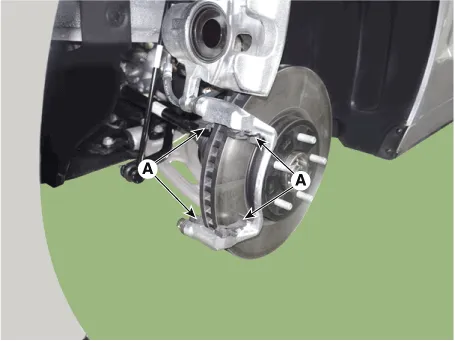
| 7. |
Remove the front brake disc (A) by loosening the screws.
|

| Inspection |
Front Brake Disc Thickness Check
| 1. |
Check the brake disc for damage and cracks. |
| 2. |
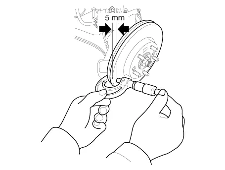
Remove all rust and contamination from the surface, and measure the disc thickness at 8 points, at least, of same distance (5mm) from the brake disc outer circle.
|
| 3. |
If wear exceeds the limit, replace the discs and pad assembly left and right of the vehicle. |
Front Brake Disc Runout Check
| 1. |
Place a dial gauge about 5mm (0.20 in) from the outer circumference of the brake disc, and measure the runout of the disc.
|

| 2. |
If the runout of the brake disc exceeds the limit specification, replace the disc, and then measure the runout again. |
| 3. |
If the runout does not exceed the limit specification, install the brake disc after turning it 180° and then check the runout of the brake disc again. |
| Installation |
| 1. |
Install in the reverse order of removal. |
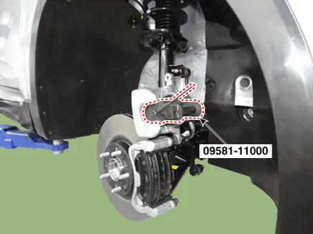
| 2. |
Use a SST (09581-11000) when installing the brake caliper assembly.
|
| 3. |
After installation, bleed the brake system. (Refer to Brake System - "Brake Bleeding Prcoedures") |
| 4. |
Check the brake oil leakage and pedal operating condition. |
Components and components location Components 1. Caliper body 2. Caliper carrier 3. Pad inner shim 4. Brake pad 5.
Components and components location Components [EPB Apply] 1. EPB Actuator 2. Caliper body 3. Caliper carrier 4.
Other information:
Kia Optima DL3 2019-2026 Service and Repair Manual: Power Door Lock Module
Repair procedures Inspection When prying with a flat-tip screwdriver or use a prying trim tool, wrap it with protective tape, and apply protective tape around the related parts, to prevent damage.
Kia Optima DL3 2019-2026 Service and Repair Manual: Walk-in Switch
Components and components location Component Location 1. Walk-in switch Repair procedures Removal When prying with a flat-tip screwdriver or use a prying trim tool, wrap it with protective tape, and apply prote
Categories
- Manuals Home
- Kia Optima Owners Manual
- Kia Optima Service Manual
- Timing Chain
- Body Electrical System
- Instrument panel overview
- New on site
- Most important about car
