Kia Optima DL3: Brake System
Service data
| Service Data |
| Service data |
|
Item |
Specification |
|
|
Master cylinder |
Cylinder I.D. |
Ø 22.22 mm (0.874 in) |
|
Piston stroke |
45 ± 1 mm (1.77 in ± 0.87 in) |
|
|
Fluid level switch |
Provided |
|
|
Brake booster |
Type |
11.0" Single |
|
Boosting ratio |
10.5:1 |
|
|
Front brake 16 inch (Disc) |
Type |
Ventilated disc |
|
Disc O.D. |
Ø 305 mm (12.00 in) |
|
|
Disc thickness |
25 mm (0.98 in) |
|
|
Cylinder type |
Single |
|
|
Cylinder I.D. |
Ø 60.6 mm (2.38 in) |
|
|
Front brake 17 inch (Disc) |
Type |
Ventilated disc |
|
Disc O.D. |
Ø 325 mm (12.79 in) |
|
|
Disc thickness |
30 mm (1.18 in) |
|
|
Cylinder type |
Single |
|
|
Cylinder I.D. |
Ø 60.6 mm (2.38 in) |
|
|
Rear brake 15 inch (Disc) / Foot pedal parking brake type |
Type |
Solid disc |
|
Disc O.D. |
Ø 284 mm (11.18 in) |
|
|
Disc thickness |
10 mm (0.39 in) |
|
|
Cylinder type |
Single |
|
|
Cylinder I.D. |
Ø 38.15 mm (1.50 in) |
|
|
Rear brake 15 inch (Disc) / Electirc parking brake type |
Type |
Solid disc |
|
Disc O.D. |
Ø 284 mm (11.18 in) |
|
|
Disc thickness |
10 mm (0.39 in) |
|
|
Cylinder type |
Single |
|
|
Cylinder I.D. |
Ø 38.00 mm (1.49 in) |
|
|
Rear brake 16 inch (Disc) / Electirc parking brake type |
Type |
Solid disc |
|
Disc O.D. |
Ø 300 mm (11.81 in) |
|
|
Disc thickness |
10 mm (0.39 in) |
|
|
Cylinder type |
Single |
|
|
Cylinder I.D. |
Ø 38.00 mm (1.49 in) |
|
| Specification (ESC) |
|
Part |
Item |
Standard value |
Remark |
|
HECU |
System |
4 Channel 4 Sensor control system |
Total control (ABS, TCS, EBD, ESC) |
|
Type |
Motor, valve relay intergrated type |
ECU, TCU and CAN |
|
|
Operating Voltage |
10V - 16V |
|
|
|
Operating Temperature |
-40°C - 110°C |
|
|
|
Motor power |
310W [Normal] / 370W [Plus] |
|
|
|
Active Wheel speed sensor (ABS) |
Supply voltage |
Front : DC 4.25 - 20V |
|
|
Rear : DC 4.5 - 20V |
|||
|
Output current low |
Front : 5.95 - 8.05 mA |
Typ .7 mA |
|
|
Rear : 5.9 - 8.4 mA |
|||
|
Output current high |
Front : 11.9 - 16.1 mA |
Typ .14 mA |
|
|
Rear : 11.8 - 16.8 mA |
|||
|
Output range |
Front : 1 - 2500 Hz |
|
|
|
Rear : 0 - 2500 Hz |
|||
|
Tone wheel |
Front : 48 teeth, Rear : 47 teeth |
|
|
|
Air gap |
0.4 - 1.0 mm |
|
|
|
Steering Wheel Angle Sensor |
Operating Voltage |
8V - 16V |
|
|
Current Consumption |
Max. 150 mA |
|
|
|
Output measurement range |
-780 to + 779.9° |
|
|
|
Operating Angular velocity |
0 - 1016°/sec |
|
| Service Standard |
|
Items |
Standard value |
|
Brake pedal height |
130.4 ± 3 mm (5.13 ± 0.11 in) |
|
Brake pedal Full stroke |
176 mm (6.93 in) |
|
Stop lamp switch clearance |
1 - 2 mm (0.04 in - 0.08 in) |
|
Brake pedal free play |
2 - 4 mm (0.08 in - 0.16 in) |
|
Front brake disc pad thickness |
11 mm (0.43 in) |
|
Front brake disc pad service limit |
2.0 mm (0.07 in) |
|
Front brake disc thickness [16 inch] |
25 mm (0.98 in) |
|
Front brake disc service limit [16 inch] |
23 mm (0.90 in) |
|
Front brake disc thickness [17 inch] |
30 mm (1.18 in) |
|
Front brake disc service limit [17 inch] |
28 mm (1.10 in) |
|
Rear brake disc pad thickness |
10 mm (0.39 in) |
|
Rear brake disc pad service limit |
2.0 mm (0.07 in) |
|
Rear brake disc thickness [15 inch] |
10 mm (0.39 in) |
|
Rear brake disc thickness [16 inch] |
10 mm (0.39 in) |
Tightening torque
| Tightening Torque |
|
Items |
N.m |
kgf.m |
lb-ft |
|
Master cylinder to brake booster |
9.8 - 15.6 |
1.0 - 1.6 |
7.2 - 11.6 |
|
Brake booster mounting nuts |
12.7 - 17.6 |
1.3 - 1.8 |
9.4 - 13.0 |
|
Air bleeding screw |
6.9 - 12.7 |
0.7 - 1.3 |
5.1 - 9.4 |
|
Brake tube flare nut, brake hose |
13.7 - 16.7 |
1.4 - 1.7 |
10.0 - 12.3 |
|
Front caliper guide rod bolts |
21.6 - 31.4 |
2.2 - 3.2 |
15.9 - 23.1 |
|
Rear caliper guide rod bolts |
21.6 - 31.4 |
2.2 - 3.2 |
15.9 - 23.1 |
|
Front caliper assembly mounting bolt |
98.1 - 117.6 |
10.0 - 12.0 |
72.3 - 86.8 |
|
Rear caliper assembly mounting bolt |
78.5 - 98.1 |
8.0 - 10.0 |
57.9 - 72.3 |
|
Brake hose to caliper |
24.5 - 29.4 |
2.5 - 3.0 |
18.1 - 21.7 |
|
Brake pedal member bracket nut |
16.7 - 25.5 |
1.7 - 2.6 |
12.3 - 18.8 |
|
Wheel speed sensor mounting bolt |
6.9 - 10.8 |
0.7 - 1.1 |
5.1 - 7.9 |
|
HECU bracket mounting nut |
19.6 - 29.4 |
2.0 - 3.0 |
14.4 - 21.7 |
Lubricant
| Lubricants |
|
Items |
Recommended |
Quantity |
|
Brake fluid |
DOT 4 |
414 ± 20cc |
|
Brake pedal bushing and bolt |
Chassis grease |
As required |
In order to maintain the best braking performance and ABS / ESC performance of the vehicle, please use genuine parts that meet the specifications. ( Standard : SAE J1704 DOT-4 LV, ISO4925 CLASS-6, FMVSS 116 DOT-4) |

Special service tools
| Special Service Tools |
|
Tool Name / Number |
Illustration |
Description |
|
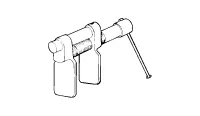
Piston expander 09581-11000 |
|
Spreading the front disc brake piston. |
|
Piston adjuster 09580-0U000 |
|
Spreading the rear disc brake piston. |
|
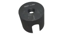
Sensor cap installer 09527-AL400 |
|
Used for installing wheel speed sensor cap (Sensor cap : Φ72.6) |

Troubleshooting
| Troubleshooting |
| Problem Symptoms Table |
Use the table below to help you find the cause of the problem. The numbers indicate the priority of the likely cause of the problem.
Check each part in order.
If necessary, replace these parts.
|
Symptom |
Possible cause |
Countermeasure |
|
Lower pedal or sponge pedal |
Brake system (oil leakage) |
Repair |
|
Brake system (air inflow) |
Perform air bleeding procedure |
|
|
Piston seal (worn out or damaged) |
Replace |
|
|
Rear brake shoe separation (faulty adjustment) |
Adjust |
|
|
Master cylinder (malfunction) |
Replace |
|
|
Brake drag |
Brake pedal free separation (minimum) |
Adjust |
|
Parking brake cable length (adjustment) |
Adjust |
|
|
Parking brake cable (sticking) |
Repair |
|
|
Rear brake shoe separation (adjustment) |
Adjust |
|
|
Pad and lining (twisted or cracked) |
Replace |
|
|
Piston (sticking) |
Replace |
|
|
Piston (frozen) |
Replace |
|
|
Anker or return spring (malfunction) |
Replace |
|
|
Booster system (leakage of vacuum) |
Repair |
|
|
Master cylinder (malfunction) |
Replace |
|
|
Uneven brake |
Piston (sticking) |
Replace |
|
Pad and lining (oil stain, cracked or twisted) |
Replace |
|
|
Heavy pedal and brake trouble |
Brake system (oil leakage, air inflow) |
Perform air bleeding procedure |
|
Pad or lining (worned out) |
Replace |
|
|
Pad or lining (cracked or twisted) |
Replace |
|
|
Rear brake shoe separation (adjustment trouble) |
Adjust |
|
|
Pad or lining (oil stain) |
Replace |
|
|
Pad or lining (slippery) |
Replace |
|
|
Booster system (leakage of vacuum) |
Repair |
|
|
Noise from brake |
Pad or lining (cracked or twisted) |
Replace |
|
Looseness of wheel bolt and caliper |
Adjust |
|
|
Pad sliding trouble (Pad uneven worn out) |
Replace |
|
|
Pad or lining (dirty) |
Cleaning |
|
|
Pad or lining (slippery) |
Pad replacement |
|
|
Anker or return spring (malfunction) |
Replace |
|
|
Brake pad shim (damaged) |
Replace |
|
|
Hold down spring (damaged) |
Replace |
|
|
Foreign substance stucked between disc and pad |
Cleaning |
|
|
Corrosion on disc |
Test drive vehicle to get rid of corrosion between rotor and pads. |
|
|
Caved disc |
Replace |
|
|
Poor braking performance (at highway speeds) |
Pad or lining (worned out) |
Replace |
|
Master cylinder (malfunction) |
Replace |
|
|
Brake vibration |
Brake booster (vacuum leak) |
Repair |
|
Pedal free separation |
Adjust |
|
|
Master cylinder (malfunction) |
Replace |
|
|
Damaged on master cylinder cap |
Replace |
|
|
Damaged on brake line |
Replace |
|
|
Caliper returning trouble (while tire is turning, check for noise) |
Replace |
|
|
Warped rotor |
Replace |
Brake bleeding procedures
| Brake System Bleeding |
1st Air Bleeding (Normal Brake System)
|
| 1. |
Make sure the brake fluid in the reservoir is at the MAX (upper) level line. |
| 2. |
Have someone slowly pump the brake pedal several times, and then apply pressure. |
| 3. |
Loosen the right-rear brake bleed screw (A) to allow air to escape from the system. Then tighten the bleed screw securely.
[Front]
[Rear]
|


| 4. |
Repeat the procedure for wheel in the sequence shown below until air bubbles no longer appear in the fluid. |
| 5. |
Follow the sequence as shown below.
|

2nd Air Bleeding (ESC System air bleeding procedures)
This procedure should be followed to ensure adequate bleeding of air and filling of the ESC unit, brake lines and master cylinder with brake fluid.
| 1. |
Remove the reservoir cap and fill the brake reservoir with brake fluid.
|
| 2. |
Connect a clear plastic tube to the wheel cylinder bleeder plug and insert the other end of the tube into a half filled clear plastic bottle. |
| 3. |
Connect the diagnostic tool to the data link connector located underneath the dash panel. |
| 4. |
Select and operate according to the instructions on the diagnostic tool screen.
|


| 5. |
Have someone slowly pump the brake pedal several times, and then apply pressure. |
| 6. |
Pump the brake pedal several times, and then loosen the bleeder screw until fluid starts to run out without bubbles. Then close the bleeder screw (A).
[Front]
[Rear]
|
| 7. |
Repeat the procedure for wheel in the sequence shown below until air bubbles no longer appear in the fluid.
|
| 8. |
Refill the master cylinder reservoir to MAX (upper) level line. |
3rd Air Bleeding
| 1. |
Repeat 1st air bleeding (Normal Brake System) once. |
- Brake System
- Brake Booster
- Master Cylinder
- Brake Line
- Brake Pedal
- Stop Lamp Switch
- Front Brake Caliper
- Front Brake Disc
- Rear Brake Caliper
- Rear Brake Disc
- Brake Pad
- Parking Brake System
- ESC (Electronic Stability Control) System
Description and operation Description The Seat Belt Pretensioners (BPT) are installed inside center pillar (LH & RH). When a vehicle crashes with a certain degree of frontal impact, the pretensioner seat belt helps to reduce the severity of injury to the front seat occupants by retracting the seat belt webbing.
Repair procedures Operation and Leakage Check Check all of the following items: Component Procedure Brake Booster (A) Check brake operation by applying the brakes during a test drive.
Other information:
Kia Optima DL3 2019-2026 Service and Repair Manual: Smart Key Unit
Schematic diagrams Connector and Terminal Function Pin Function Connector A Connector B Connector C Connector D 1 - Front washer switch (Output) - Driver outside handle switch (Input)
Kia Optima DL3 2019-2026 Service and Repair Manual: Temperature Control Actuator
Components and components location Components Location 1. Temperature control actuator [LH] 2. Temperature control actuator [RH] Description and operation Description The temperature control actuator is located at the heater unit.
Categories
- Manuals Home
- Kia Optima Owners Manual
- Kia Optima Service Manual
- Engine Control / Fuel System
- Identification Numbers
- Heating, Ventilation and Air Conditioning
- New on site
- Most important about car
