Kia Optima DL3: Brake System / Front Brake Caliper
Components and components location
| Components |
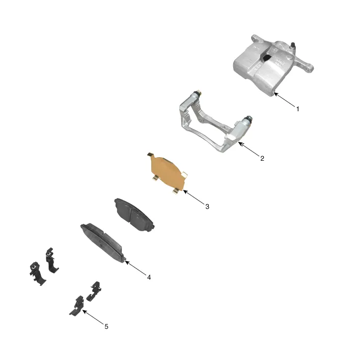
| 1. Caliper body 2. Caliper carrier 3. Pad inner shim |
4. Brake pad 5. Pad retainer |
Repair procedures
| Removal |
| 1. |
Disconnect the (-) battery terminal. |
| 2. |
Remove the front wheel and tire. (Refer to Suspension System - "Wheel") |
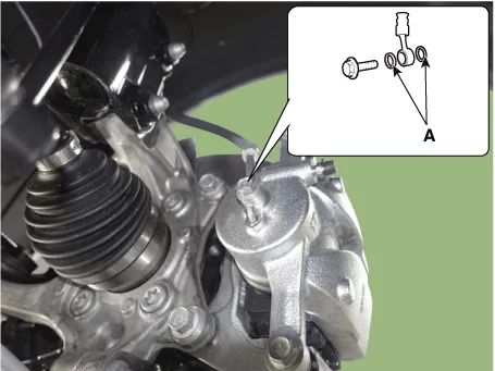
| 3. |
Remove the hose after loosening the brake hose bolt (A) from the caliper.
|


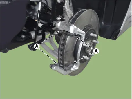
| 4. |
Remove the caliper body (A) by loosening the guide rod bolt.
|
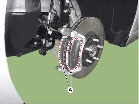
| 5. |
Remove the pad retainer (A).
|
| 6. |
Remove the caliper carrier (A) by loosening the caliper mouniting bolts.
|
| 7. |
Remove the caliper carrier (A) by loosening the caliper mouniting bolts.
|

| Installation |
| 1. |
Install in the reverse order of removal. |
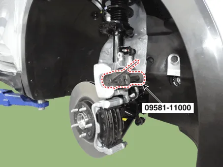
| 2. |
Use a SST (09581-11000) when installing the brake caliper assembly.
|
| 3. |
After installation, bleed the brake system. (Refer to Brake system - "Brake Bleeding Procedures") |
| 4. |
Check the brake oil leakage and pedal operating condition. |
Components and components location Components 1. Brake member assembly 2. Stop lamp switch 3. Brake pedal arm assembly 4.
Components and components location Components 1. Front Brake Caliper 2. Front Brake Disc 3. Front Axle Repair procedures Removal 1.
Other information:
Kia Optima DL3 2019-2026 Service and Repair Manual: High Mounted Stop Lamp
Repair procedures Removal 1. Disconnect the negative battery terminal. 2. Remove the roof trim assembly. (Refer to Body - "Roof Trim Assembly") 3. Disconnect the high mounted stop lamp connector (A).
Kia Optima DL3 2019-2026 Service and Repair Manual: Compressor
Description and operation Description The compressor is the power unit of the A/C system. It is located on the side of engine block and driven by a V-belt of the engine. The compressor changes low pressure and low temperature refrigerant gas into high pressure and high temperature refrigerant gas.
Categories
- Manuals Home
- Kia Optima Owners Manual
- Kia Optima Service Manual
- Suspension System
- Motor Driven Power Steering
- Engine Control / Fuel System
- New on site
- Most important about car
