Kia Optima DL3: Body (Interior and Exterior) / Front Bumper
Components and components location
| Components |
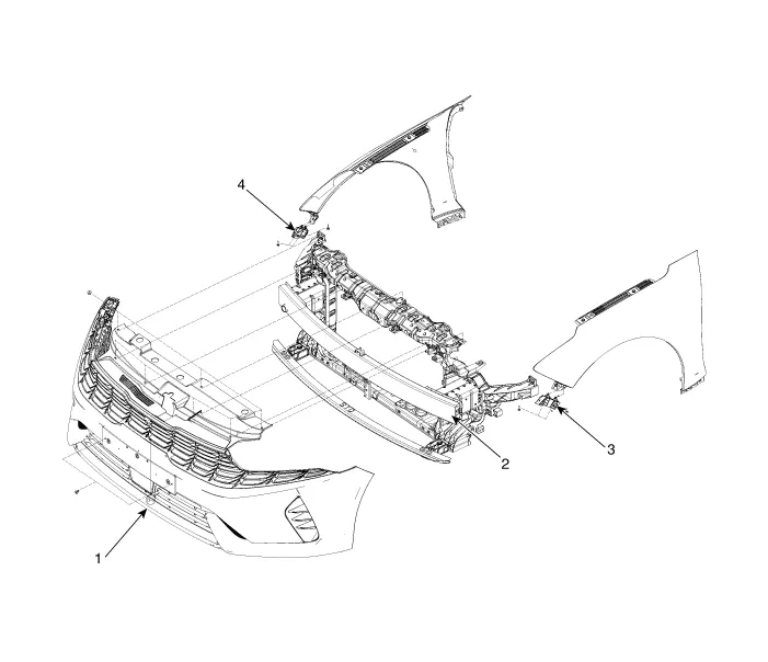
| 1. Front bumper assembly 2. Front bumper beam assembly |
3. Front bumper side bracket
[LH] 4. Front bumper side bracket [RH] |
Repair procedures Replacement • When removing with a flat-tip screwdriver or remover, wrap protective tape around the tools to prevent damage to components.
Components and components location Component Location 1. Front bumper assembly Repair procedures Replacement • When removing with a flat-tip screwdriver or remover, wrap protective tape around the tools to prevent damage to components.
Other information:
Kia Optima DL3 2019-2026 Service and Repair Manual: Power Door Locks
C
Kia Optima DL3 2019-2026 Service and Repair Manual: Walk-in Switch
Components and components location Component Location 1. Walk-in switch Repair procedures Removal When prying with a flat-tip screwdriver or use a prying trim tool, wrap it with protective tape, and apply prote
Categories
- Manuals Home
- Kia Optima Owners Manual
- Kia Optima Service Manual
- Instrument panel overview
- Body Electrical System
- Floor Console Assembly
- New on site
- Most important about car
