
Kia Optima DL3: Front Bumper / Front Bumper Assembly
Components and components location
| Component Location |
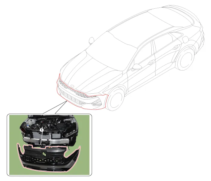
| 1. Front bumper assembly |
Repair procedures
| Replacement |
|

| 1. |
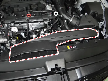
Remove the air duct (A).
|
| 2. |
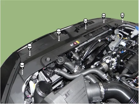
Loosen the radiator upper cover mounting clips.
|
| 3. |
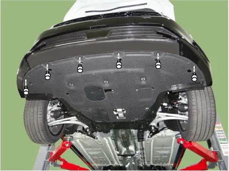
Loosen the front bumper lower clips.
|
| 4. |
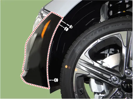
Loosen the pin-type retainers and screws on the side of front bumper, detach the side part of front bumper.
|

| 5. |
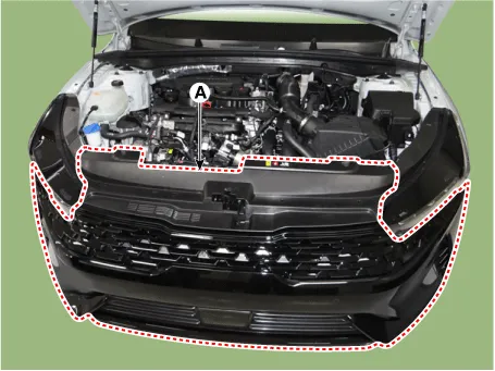
Remove the front bumper assembly (A).
|
| 6. |
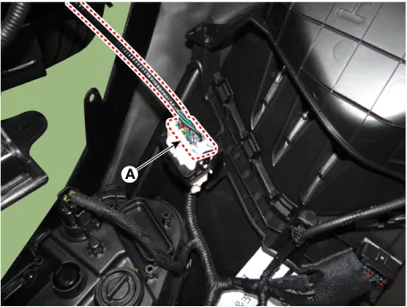
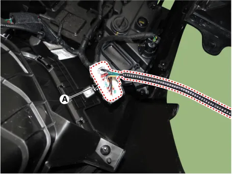
Press the lock pin and separate the front bumper main connector (A). [LH]
[RH]
|
| 7. |
To install, reverse the removal procedure.
|

Components and components location Components 1. Front bumper assembly 2. Front bumper beam assembly 3. Front bumper side bracket [LH] 4.
Components and components location Component Location 1. Radiator grill Repair procedures Replacement • When removing with a flat-tip screwdriver or remover, wrap protective tape around the tools to prevent damage to components.
Other information:
Kia Optima DL3 2019-2026 Service and Repair Manual: Compressor oil
Repair procedures Oil Specification 1. The HFC-134a system requires synthetic (PAG) compressor oil whereas the R-12 system requires mineral compressor oil. The two oils must never be mixed. 2. Compressor (PAG) oil varies according to compressor model.
Kia Optima DL3 2019-2026 Service and Repair Manual: Refrigerant Line
Components and components location Components Location 1. Suction & Liquid tube assembly 2. Discharge hose Repair procedures Replacement 1. If the compressor is marginally operable, run the engine at idle speed, and let the air conditioning work for a few minute
Categories
- Manuals Home
- Kia Optima Owners Manual
- Kia Optima Service Manual
- Headlamps
- Air bag collision sensors
- Restraint
- New on site
- Most important about car
