
Kia Optima DL3: Front Bumper / Front Bumper Assembly
Components and components location
| Component Location |
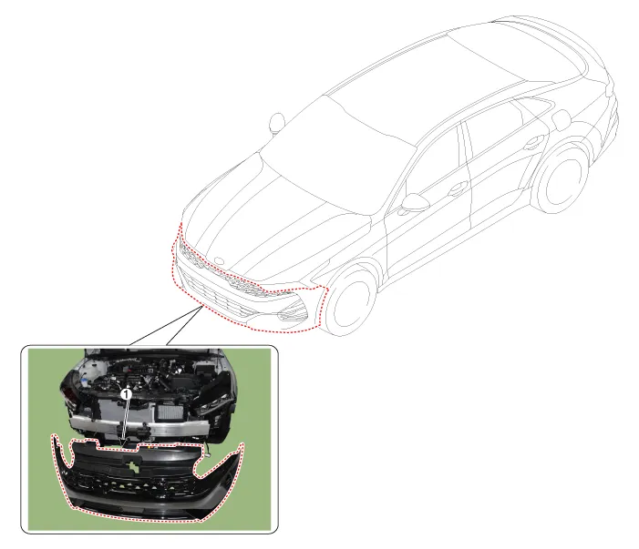
| 1. Front bumper assembly |
Repair procedures
| Replacement |
|

| 1. |
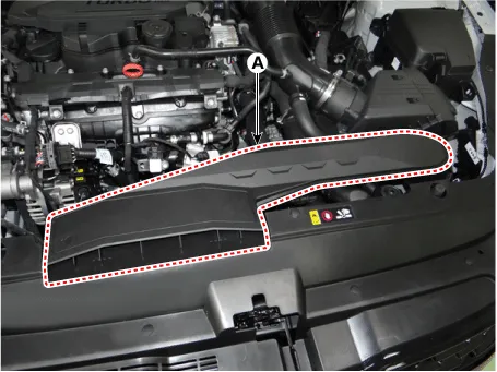
Remove the air duct (A).
|
| 2. |
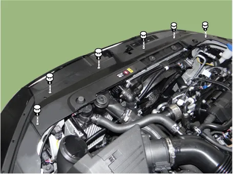
Loosen the radiator upper cover mounting clips.
|
| 3. |
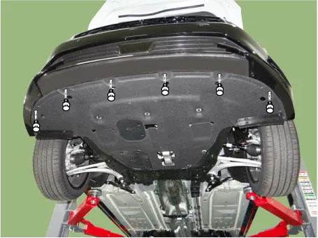
Loosen the front bumper lower clips.
|
| 4. |
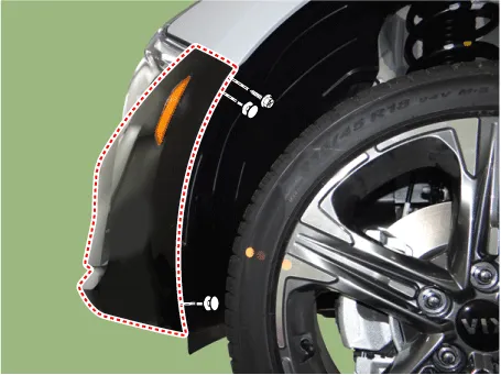
Loosen the pin-type retainers and screws on the side of front bumper, detach the side part of front bumper.
|

| 5. |
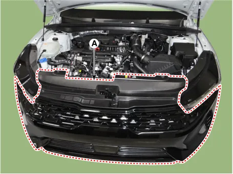
Remove the front bumper assembly (A).
|
| 6. |
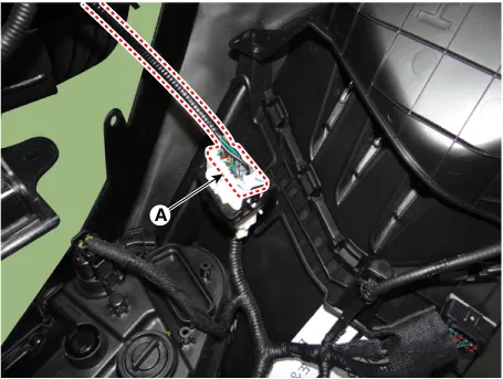
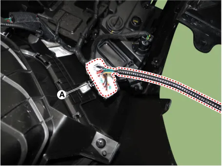
Press the lock pin and separate the front bumper main connector (A). [LH]
[RH]
|
| 7. |
To install, reverse the removal procedure.
|

Components and components location Components 1. Front bumper assembly 2. Front bumper beam assembly 3. Front bumper side bracket [LH] 4.
Components and components location Component Location 1. Radiator grill Repair procedures Replacement • When removing with a flat-tip screwdriver or remover, wrap protective tape around the tools to prevent damage to components.
Other information:
Kia Optima DL3 2019-2026 Service and Repair Manual: Ventilated and Heated Seat Switch
Schematic diagrams Connector and Terminal Function [Front Seat] [Ventilation+Heater Type / Non-Heater Type] Pin Function Pin Function Ventilation+Heater Type Non-Heater Type Ventilation+Heater Type Non-Heater Type
Kia Optima DL3 2019-2026 Service and Repair Manual: Mode Control Actuator
Components and components location Components Location 1. Mode control actuator Description and operation Description The mode control actuator is located at the heater unit. It adjusts the position of the mode door by operating the mode control actuator based on the signal of the A/C co
Categories
- Manuals Home
- Kia Optima Owners Manual
- Kia Optima Service Manual
- Suspension System
- Air bag collision sensors
- Identification Numbers
- New on site
- Most important about car
