
Kia Optima DL3: Front Door / Front Door Inside Handle
Repair procedures
| Replacement |
| 1. |
Remove the front door trim. (Refer to Front Door - "Front Door Trim") |
| 2. |
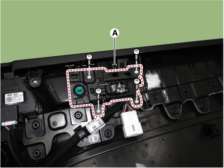
Loosen the mounting screws and remove the front door inside handle (A).
|

| 3. |
To install, reverse the removal procedure.
|

Components and components location Component Location 1. Front door module Repair procedures Replacement • When removing with a flat-tip screwdriver or remover, wrap protective tape around the tools to prevent damage to components.
Components and components location Component Location 1. Front door outside handle Repair procedures Replacement • When removing with a flat-tip screwdriver or remover, wrap protective tape around the tools to prevent damage to components.
Other information:
Kia Optima DL3 2019-2026 Service and Repair Manual: Hazard Lamp Switch
Schematic diagrams Connector and Terminal Function Repair procedures Removal 1. Disconnect the negative battery terminal. 2. Remove the crash pad garnish [RH]. (Refer to Body - "Crash Pad Garnish") 3.
Kia Optima DL3 2019-2026 Service and Repair Manual: Smart Key System
Specifications Specifications Smart Key Unit Items Specification Rated voltage DC 12 V Operation voltage DC 9 - 16 V Operation temperature -40 to 185°F (-40 to 85°C) RF Receiver Items
Categories
- Manuals Home
- Kia Optima Owners Manual
- Kia Optima Service Manual
- Lift And Support Points
- Restraint
- CVVT Oil Control Valve (OCV)
- New on site
- Most important about car
