Kia Optima DL3: Body Electrical System / Fuel Filler Door
Components and components location
| Components Location |
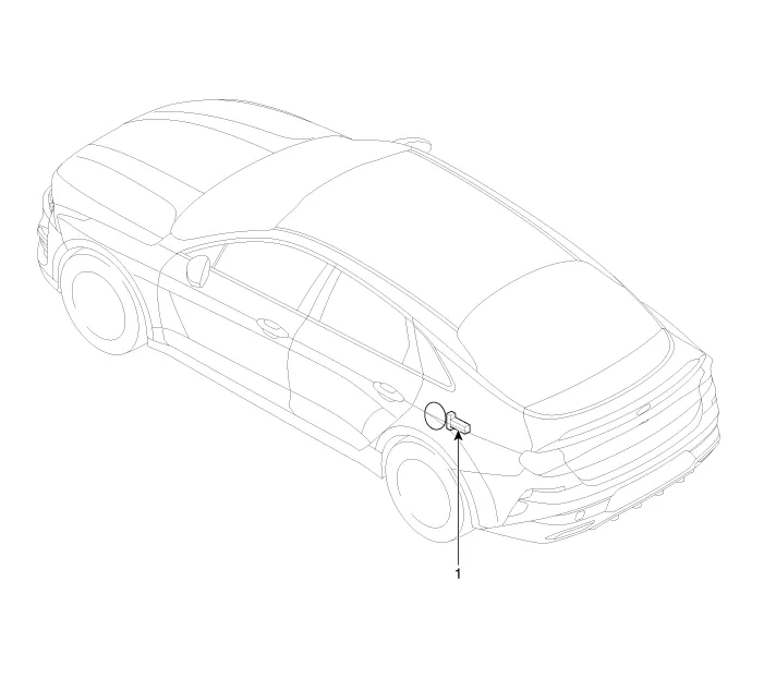
| 1. Fuel filler door unlock actuator
|
Components and components location Component Location 1. Integrated central control unit (ICU) Description and operation Description Integrated Central control Unit (ICU) combines both Smart Junction Block (SJB) and Integrated Gateway & Power Control Module (IGPM) System Block Diagram Function Item Function Function Switch input Receives switch inputs and then sends the switch status to each module through CAN message.
Repair procedures Removal 1. Disconnect the negative battery terminal. 2. Remvoe the fuel door housing.
Other information:
Kia Optima DL3 2019-2026 Service and Repair Manual: Panorama Sunroof
C
Kia Optima DL3 2019-2026 Service and Repair Manual: Power Windows
Components and components location Component Location 1. Power window main switch 2. Rear window main switch 3. Front power window motor 4. Rear power window motor Description and operation Description Power Window Safety Function When the driver or passenger p
Categories
- Manuals Home
- Kia Optima Owners Manual
- Kia Optima Service Manual
- Charging System
- Restraint
- Battery
- New on site
- Most important about car
