Kia Optima DL3: Fuses And Relays / Integrated Central Control Unit (ICU)
Components and components location
| Component Location |
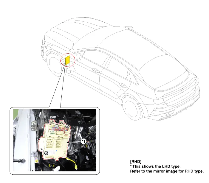
| 1. Integrated central control
unit (ICU) |
Description and operation
| Description |
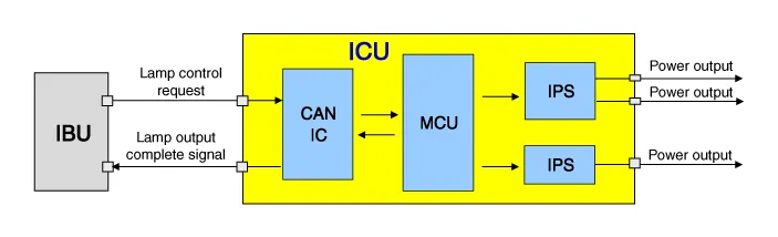
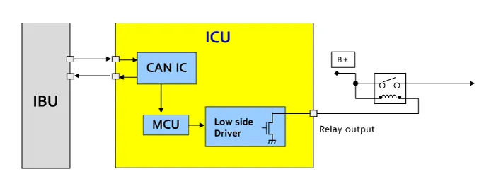
Integrated Central control Unit (ICU) combines both Smart Junction Block (SJB) and Integrated Gateway & Power Control Module (IGPM)
| System Block Diagram |
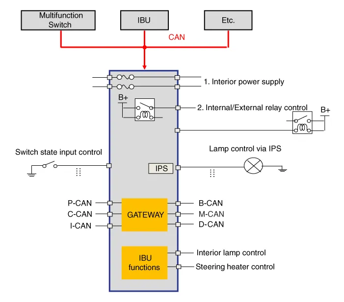
| Function |
|
Item |
Function |
|
|
Function |
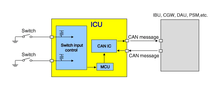
Switch input |
Receives switch inputs and then sends the switch status to each module through
CAN message. |
|
Lamp control |
Controls lamp with the IPS by receiving command from IBU via CAN message.
|
|
|
Internal relay control |
Controls internal relay by receiving command from IBU via CAN message.
|
|
|
External relay control |
Controls external relay by receiving command from IBU via CAN message.
|
|
|
Dark current shut off system |
The system automatically shuts off the power to be provided with components
for reducing useless dark current according to the vehicle operating conditions
such as shipment and long-term parking. |
|
|
Trouble diagnosis |
Diagnose status of loads controlled by IPS. |
|
|
Gateway |
Transmits signals among the modules connected to the different networks
in the vehicle. |
|
※ The ICU does not judge logic, it is operated only by CAN commands of other modules.
▶ Self-Logic Function : Hazard lamp, Stop lamp, Tailgate room lamp, Steering heater, Door lock/unlock
Switch Input
| 1. |
Operation Function ▶ Hazard lamp switch, Seat belt switch, Tailgate switch, Door switch, etc. |
| 2. |
Operation Description
|
IPS Lamp control
| 1. |
Operation Function ▶ Headlamp low/high, Turn signal lamp, DRL lamp, Internal/External tail lamp, Stop lamp, etc. |
| 2. |
Operation Description
|
Internal relay control
| 1. |
Operation Function ▶ Burglar alarm horn, Tailgate, Power window, etc. |
| 2. |
Operation Description
|

External relay control
| 1. |
Operation Function ▶ Headlamp high solenoid, Rear fog, Rear Glass Defogger, etc. |
| 2. |
Operation Description
|
Dark current shut off system
| 1. |
Operation Description
|

Repair procedures
| Inspection |
Fuse Inspection
| 1. |
Check that the fuse holders are loosely held and that the fuses are securely fixed by the holders. |
| 2. |
Check that each fuse circuit has the exact fuse capacity. |
| 3. |
Check the fuses for any damage.
|

Diagnosis with KDS
| 1. |
In the body electrical system, failure can be quickly diagnosed by using the vehicle diagnostic system (KDS). The diagnostic system (KDS) provides the following information.
|
| 2. |
Select the 'Car model' and the 'Integrated Central Control Unit (ICU)' to be checked in order to check the vehicle with the tester. |
| 3. |
Select the 'Current Data' menu to search the current state of the input/output data. |
| 4. |
To force actuate the input value of the module to be checked, select option 'Actuation Test' |
| 5. |
If you want to change user option, select "user option". |
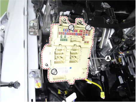
| Removal |
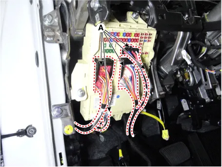
| 1. |
Disconnect the negative battery terminal. |
| 2. |
Remove the mood lamp unit. (Refer to Lighting System - "Mood Lamp Unit") |
| 3. |
Disconnect the ICU connectors (A).
|
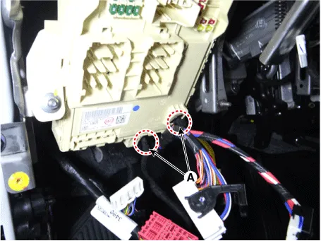
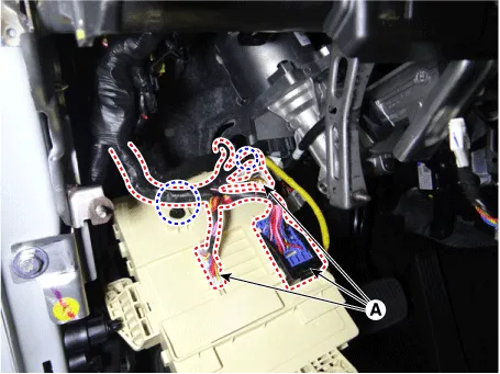
| 4. |
Remove the fixing clips (A).
|
| 5. |
Remove the ICU (A) by loosening the mounting nuts.
|
| 6. |
Disconnect the connectors (A) from the ICU and then remove the wiring mounting clips.
|
| Installation |
| 1. |
Install in the reverse order of removal. |
Components and components location Components Location 1. Engine room junction block Repair procedures Inspection Power Relay (Type A) Check for continuity between the terminals.
Components and components location Components Location 1. Fuel filler door unlock actuator
Other information:
Kia Optima DL3 2019-2026 Service and Repair Manual: Wiper Motor
Schematic diagrams Connector and Terminal Function Pin Function 1 Ground (-) 2 Parking 3 Power (+) 4 Low 5 High Repair procedures Remova
Kia Optima DL3 2019-2026 Service and Repair Manual: Temperature Control Actuator
Components and components location Components Location 1. Temperature control actuator [LH] 2. Temperature control actuator [RH] Description and operation Description The temperature control actuator is located at the heater unit.
Categories
- Manuals Home
- Kia Optima Owners Manual
- Kia Optima Service Manual
- Engine Control Module (ECM)
- Brake System
- Headlamps
- New on site
- Most important about car
