Kia Optima DL3: Seat Electrical / Heated Seats Only
Components and components location
| Components |
| Front Seat Heater |
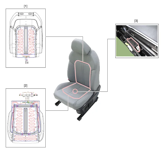
| 1. Front seat back heater 2. Front seat cushion heater |
3. Front seat heater unit / ventilation
unit |
| Rear Seat Heater |

| 1. Rear seat heater unit 2. Rear seat back heater |
3. Rear seat cushion heater
|
Schematic diagrams
| Connector and Terminal Function |
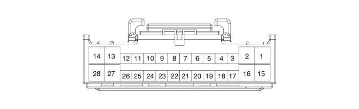
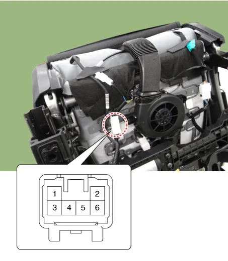
Front Seat Heater Unit
|
Pin |
Function |
Pin |
Function |
|
1 |
Battery (+) |
15 |
Battery (+) |
|
2 |
Driver heater power (+) |
16 |
Passenger heater power (+) |
|
3 |
IGN1 |
17 |
IGN2 |
|
4 |
CAN (Low) |
18 |
- |
|
5 |
CAN (High) |
19 |
Detent |
|
6 |
- |
20 |
Illumination (-) |
|
7 |
Driver heater indicator (High) |
21 |
Passenger heater indicator (High) |
|
8 |
Driver heater indicator (Mid) |
22 |
Passenger heater indicator (Mid) |
|
9 |
Driver heater indicator (Low) |
23 |
Passenger heater indicator (Low) |
|
10 |
Driver heater switch |
24 |
Passenger heater switch |
|
11 |
Driver heater NTC (+) |
25 |
Passenger heater NTC (+) |
|
12 |
Driver heater NTC (-) |
26 |
Passenger heater NTC (-) |
|
13 |
Driver heater ground (-) |
27 |
Passenger heater ground (-) |
|
14 |
Ground |
28 |
Ground |
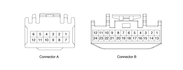
Front Seat Heater Unit (Ventilation seat unit)
|
Pin |
Function |
|
|
Connector A |
Connector B |
|
|
1 |
Driver heater ground (-) |
Driver blower speed (+) |
|
2 |
Passenger heater ground (-) |
- |
|
3 |
Driver cushion heater power (+) |
CAN (Low) |
|
4 |
Driver back heater power (+) |
CAN (High) |
|
5 |
Passenger cushion heater power (+) |
- |
|
6 |
Passenger back heater power (+) |
LIN |
|
7 |
ECU (Ground) |
Detent |
|
8 |
ECU (Ground) |
IGN1 |
|
9 |
|
Driver blower speed |
|
10 |
Passenger blower speed |
|
|
11 |
Illumination (-) |
|
|
12 |
Driver NTC (-) |
|
|
13 |
Passenger NTC (-) |
|
|
14 |
- |
|
|
15 |
- |
|
|
16 |
- |
|
|
17 |
- |
|
|
18 |
- |
|
|
19 |
- |
|
|
20 |
IGN2 |
|
|
21 |
- |
|
|
22 |
Driver NTC (+) |
|
|
23 |
Passenger NTC (+) |
|
|
24 |
- |
|
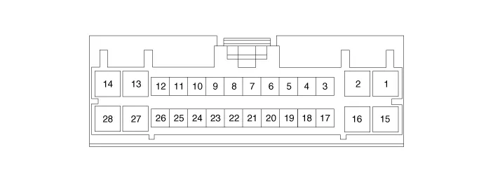
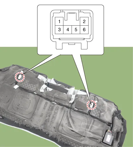
Rear Seat Heater Unit
|
Pin |
Function |
Pin |
Function |
|
1 |
Battery (+) |
15 |
Battery (+) |
|
2 |
Heater power (+)_LH |
16 |
Heater power (+)_RH |
|
3 |
IGN1 |
17 |
IGN2 |
|
4 |
CAN (Low) |
18 |
- |
|
5 |
CAN (High) |
19 |
- |
|
6 |
- |
20 |
- |
|
7 |
Heater indicator (High)_LH |
21 |
Heater indicator (High)_RH |
|
8 |
- |
22 |
- |
|
9 |
Heater indicator (Low)_LH |
23 |
Heater indicator (Low)_RH |
|
10 |
Heater switch_LH |
24 |
Heater switch_RH |
|
11 |
Heater NTC (+)_LH |
25 |
Heater NTC (+)_RH |
|
12 |
Heater NTC (-)_LH |
26 |
Heater NTC (-)_RH |
|
13 |
Heater ground (-)_LH |
27 |
Heater ground (-)_RH |
|
14 |
Ground |
28 |
Ground |
Repair procedures
| Inspection |
Driver/Passenger Seat Heater
| 1. |
Check for continuity and measure the resistance between terminals.
|
|||||||||||||||||||||||||||||||||||||
| 2. |
Operate the seat heater after connecting the connector, and then check the thermostat by measuring the temperature of seat surface.
|
||||||||||
Rear Seat Heater
| 1. |
Check for continuity and measure the resistance between terminals.
|
| 2. |
Operate the seat heater after connecting the connector, and then check the thermostat by measuring the temperature of seat surface.
|
||||||||
| Removal |
Front Seat Heater Unit
| 1. |
Remove the passenger seat assembly. (Refer to Body - "Front Seat assembly") |
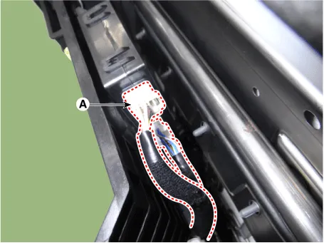
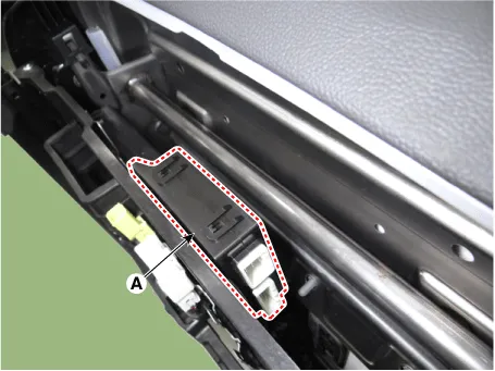
| 2. |
Disconnect the seat heater unit connector (A).
|
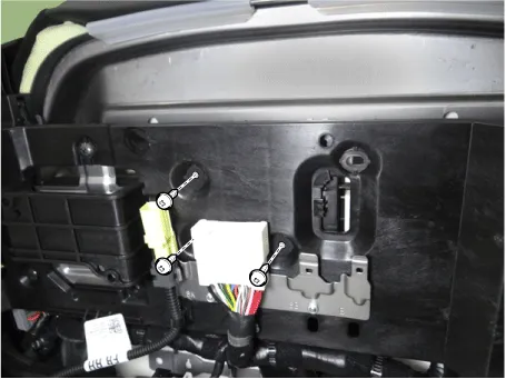
| 3. |
Remove the front seat heater unit (A) by loosening the screws.
|
Rear Seat Heater Unit
| 1. |
Disconnect the negative battery terminal. |
| 2. |
Remove the rear seat cushion assembly. (Refer to Body - "Rear Seat Assembly") |
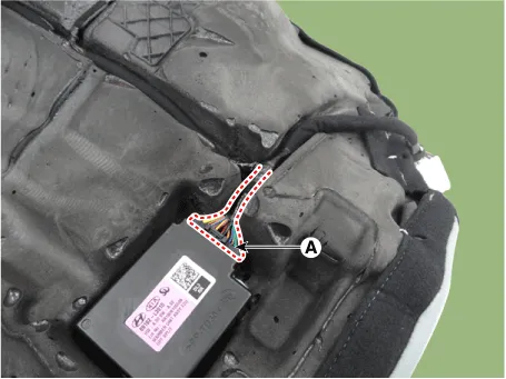
| 3. |
Disconnect the rear seat heater unit connector (A).
|
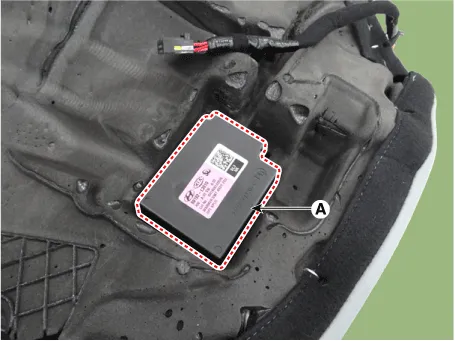
| 4. |
Remove the rear seat heater unit (A).
|
| Installation |
| 1. |
Install in the reverse order of removal. |
Schematic diagrams Connector and Terminal Function [Front Seat] [Ventilation+Heater Type / Non-Heater Type] Pin Function Pin Function Ventilation+Heater Type Non-Heater Type Ventilation+Heater Type Non-Heater Type 1 IGN1 - 9 Illumination (+) 2 - - 10 - 3 - - 11 Illumination (-) 4 Ground - 12 - 5 - 13 Steering heater mode - 6 - 14 Steering heater indicator - 7 LIN - 15 Driver mode switch (CW) 8 Ground 16 Driver mode switch (CCW) [Heater Type] Pin Function Pin Function 1 Heater indicator (High)_RH 13 Heater mode_RH 2 Heater indicator (Mid)_RH 14 - 3 Heater indicator (Low)_RH 15 - 4 - 16 Ground 5 Driver mode switch (CW) 17 - 6 Driver mode switch (CCW) 18 Illumination (-) 7 Steering heater mode 19 - 8 Steering heater indicator 20 Illumination (+) 9 Heater mode_LH 21 - 10 Heater indicator (High)_LH 22 - 11 Heater indicator (Mid)_LH 23 - 12 Heater indicator (Low)_LH 24 - [Rear Seat] [Safety Type] Pin Function Pin Function 1 Ground (Illumination -) 5 Ground 2 Door lock switch 6 Door lock indicator 3 Door unlock switch 7 Safety power window 4 Battery + (Illumination +) 8 - [Manual Type] Pin Function Pin Function 1 Ground 7 Driver window down 2 Seat warmer (High) 8 Window enble 3 Window down motor 9 Ground (Illumination -) 4 Seat warmer (Low) 10 Driver window up 5 Window up motor 11 Battery + (Illumination +) 6 Seat warmer switch 12 Battery (+) Repair procedures Inspection [Front Seat] 1.
Other information:
Kia Optima DL3 2019-2026 Service and Repair Manual: Power Window Switch
Schematic diagrams Connector and Terminal Function Power Window Main Switch Pin Function 1 B-CAN (Low) 2 B-CAN (High) 3 Ground (Assist safety) 4 Assist safety 5
Kia Optima DL3 2019-2026 Service and Repair Manual: Walk-in Switch
Components and components location Component Location 1. Walk-in switch Repair procedures Removal When prying with a flat-tip screwdriver or use a prying trim tool, wrap it with protective tape, and apply prote
Categories
- Manuals Home
- Kia Optima Owners Manual
- Kia Optima Service Manual
- Emergency trunk safety release
- Charging System
- Lift And Support Points
- New on site
- Most important about car
