Kia Optima DL3: Seat Electrical / Walk-in Switch
Components and components location
| Component Location |
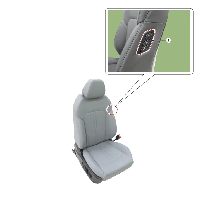
| 1. Walk-in switch |
Repair procedures
| Removal |
When prying with a flat-tip screwdriver or use a prying trim tool, wrap it with protective tape, and apply protective tape around the related parts, to prevent damage. |

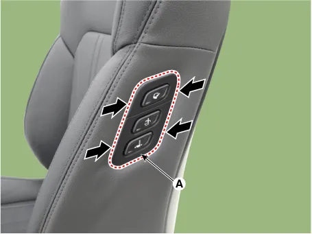
| 1. |
Remove the walk-in switch (A) by pressing the hooks.
|
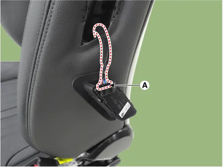
| 2. |
Disconnect the walk-in switch connector (A).
|
| Installation |
| 1. |
Install in the reverse order of removal. |
Components and components location Components 1. Lumbar support motor 2. Reclining motor 3. Front height motor 4.
Components and components location Component Location 1. Relaxion comfort switch 2. Walk-in switch 3. Relaxion comfort seat unit (RCSU) Schematic diagrams Connector and Terminal Function Pin Function Connector A Connector B 1 Battery (+) Slide motor switch (Forward) 2 Slide motor (Forward) Slide motor switch (Backward) 3 Slide motor (Backward) Relaxion comfort switch (Forward) 4 Recline motor (Forward) Relaxion comfort switch (Backward) 5 Recline motor (Backward) Rear height motor switch (Up) 6 Ground Rear height motor switch (Down) 7 Battery (+) Relaxion comfort switch 8 - Return switch 9 Rear height motor (Up) - 10 Rear height motor (Down) - 11 - Sensor power 12 Ground IGN2 13 IGN1 14 ECU (Battery +) 15 Walk-in switch Slide (Forward) 16 Walk-in switch Slide (Backward) 17 Walk-in switch Recline (Forward) 18 Walk-in switch Recline (Backward) 19 Walk-in relaxion comfort switch 20 Walk-in return switch 21 ECU (Ground) 22 - 23 - 24 Limit set power 25 Slide motor sensor 26 Recline motor sensor 27 Rear height motor sensor 28 Virtual limit set switch Repair procedures Removal Walk-in Switch 1.
Other information:
Kia Optima DL3 2019-2026 Service and Repair Manual: Smart Key Unit
Schematic diagrams Connector and Terminal Function Pin Function Connector A Connector B Connector C Connector D 1 - Front washer switch (Output) - Driver outside handle switch (Input)
Kia Optima DL3 2019-2026 Service and Repair Manual: A/C Pressure Transducer
Description and operation Description The A/C Pressure Transducer (APT) converts the pressure value of high pressure line into voltage value after measuring it. By converted voltage value, engine ECU controls the cooling fan by operating it high speed or low speed.
Categories
- Manuals Home
- Kia Optima Owners Manual
- Kia Optima Service Manual
- Brake System
- Heating, Ventilation and Air Conditioning
- Steering System
- New on site
- Most important about car
