Kia Optima DL3: Seat Electrical / Ventilated and Heated Seat Switch
Schematic diagrams
| Connector and Terminal Function |
[Front Seat]
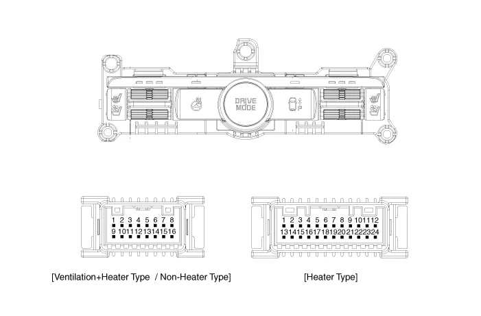
[Ventilation+Heater Type / Non-Heater Type]
|
Pin |
Function |
Pin |
Function |
||
|
Ventilation+Heater Type |
Non-Heater Type |
Ventilation+Heater Type |
Non-Heater Type |
||
|
1 |
IGN1 |
- |
9 |
Illumination (+) |
|
|
2 |
- |
- |
10 |
- |
|
|
3 |
- |
- |
11 |
Illumination (-) |
|
|
4 |
Ground |
- |
12 |
- |
|
|
5 |
- |
13 |
Steering heater mode |
- |
|
|
6 |
- |
14 |
Steering heater indicator |
- |
|
|
7 |
LIN |
- |
15 |
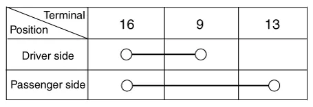
Driver mode switch (CW) |
|
|
8 |
Ground |
16 |
Driver mode switch (CCW) |
||
[Heater Type]
|
Pin |
Function |
Pin |
Function |
|
1 |
Heater indicator (High)_RH |
13 |
Heater mode_RH |
|
2 |
Heater indicator (Mid)_RH |
14 |
- |
|
3 |
Heater indicator (Low)_RH |
15 |
- |
|
4 |
- |
16 |
Ground |
|
5 |
Driver mode switch (CW) |
17 |
- |
|
6 |
Driver mode switch (CCW) |
18 |
Illumination (-) |
|
7 |
Steering heater mode |
19 |
- |
|
8 |
Steering heater indicator |
20 |
Illumination (+) |
|
9 |
Heater mode_LH |
21 |
- |
|
10 |
Heater indicator (High)_LH |
22 |
- |
|
11 |
Heater indicator (Mid)_LH |
23 |
- |
|
12 |
Heater indicator (Low)_LH |
24 |
- |
[Rear Seat]
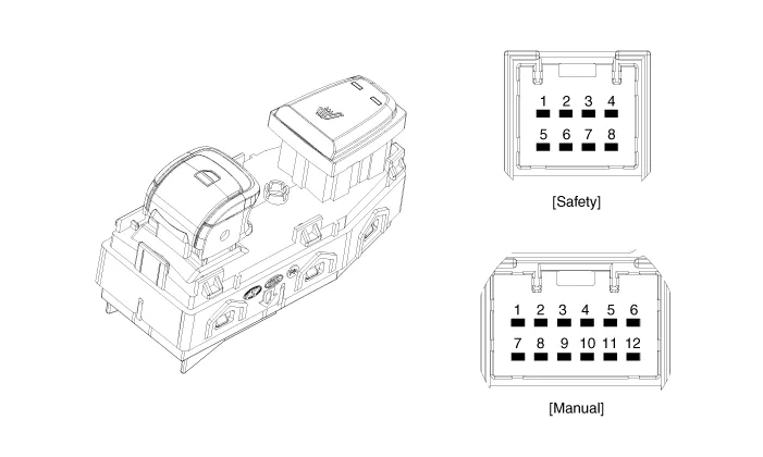
[Safety Type]
|
Pin |
Function |
Pin |
Function |
|
1 |
Ground (Illumination -) |
5 |
Ground |
|
2 |
Door lock switch |
6 |
Door lock indicator |
|
3 |
Door unlock switch |
7 |
Safety power window |
|
4 |
Battery + (Illumination +) |
8 |
- |
[Manual Type]
|
Pin |
Function |
Pin |
Function |
|
1 |
Ground |
7 |
Driver window down |
|
2 |
Seat warmer (High) |
8 |
Window enble |
|
3 |
Window down motor |
9 |
Ground (Illumination -) |
|
4 |
Seat warmer (Low) |
10 |
Driver window up |
|
5 |
Window up motor |
11 |
Battery + (Illumination +) |
|
6 |
Seat warmer switch |
12 |
Battery (+) |
Repair procedures
| Inspection |
[Front Seat]
| 1. |
Disconnect the negative battery terminal. |
| 2. |
Remove the console upper cover. (Refer to Body - "Floor Console Assembly") |
| 3. |
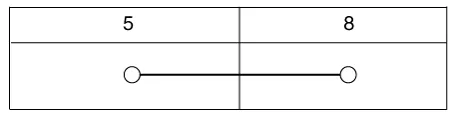
Push and hold the switch, check for continuity between signal terminal and ground terminal.
[Heater Switch]
|

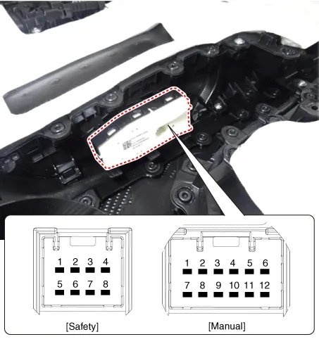
[Rear Seat]
| 1. |
Disconnect the negative battery terminal. |
| 2. |
Remove the rear door trim. (Refer to Body - "Rear Door Trim") |
| 3. |
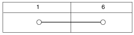
Push and hold the switch, check for continuity between signal terminal and ground terminal.
[Safety]
[Manual]
|
| Removal |
[Front Seat]
| 1. |
Disconnect the negative battery terminal. |
| 2. |
Remove the console upper cover. (Refer to Body - "Floor Console Assembly") |
| 3. |
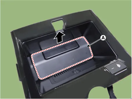
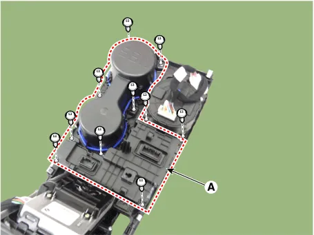
Remove the wireless power charger pad (A).
|
| 4. |
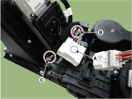
Disconnect the all connectors from the console floor switch complete. (A) : Main connector fixing fastener (B) : Console floor switch complete connector (C) : Wireless charging indicator connector
|
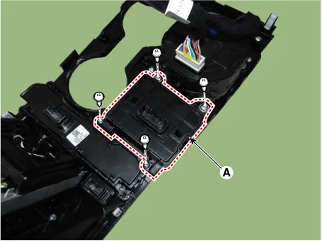
| 5. |
Remove the console cup holder assembly (A) by loosening the mounting screws.
|
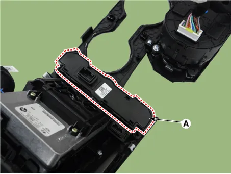
| 6. |
Remove the EPB switch assembly (A) by loosening the mounting screws.
|
| 7. |
Remove the console floor switch complete (A).
|
[Rear Seat]
| 1. |
Disconnect the negative battery terminal. |
| 2. |
Remove the rear power window switch. (Refer to Power Windows - "Power Window Switch") |
| Installation |
| 1. |
Install in the reverse order of removal. |
Components and components location Components Front Seat Heater 1. Front seat back heater 2. Front seat cushion heater 3.
Schematic diagrams Connector and Terminal Function Pin Function Connector A Connector B 1 Driver heater ground (-) Driver blower speed (+) 2 Passenger heater ground (-) - 3 Driver cushion heater power (+) CAN (Low) 4 Driver back heater power (+) CAN (High) 5 Passenger cushion heater power (+) - 6 Passenger back heater power (+) LIN 7 ECU (Ground) Detent 8 ECU (Ground) IGN1 9 Driver blower speed 10 Passenger blower speed 11 Illumination (-) 12 Driver NTC (-) 13 Passenger NTC (-) 14 - 15 - 16 - 17 - 18 - 19 - 20 IGN2 21 - 22 Driver NTC (+) 23 Passenger NTC (+) 24 - Repair procedures Removal Ventilation Seat Unit 1.
Other information:
Kia Optima DL3 2019-2026 Service and Repair Manual: Power Door Lock Module
Repair procedures Inspection When prying with a flat-tip screwdriver or use a prying trim tool, wrap it with protective tape, and apply protective tape around the related parts, to prevent damage.
Kia Optima DL3 2019-2026 Service and Repair Manual: Intake Actuator
Components and components location Components Location 1. Intake actuator Description and operation Description The intake actuator is located at the blower unit. It regulates the intake door by a signal from the control unit.
Categories
- Manuals Home
- Kia Optima Owners Manual
- Kia Optima Service Manual
- Brake System
- Motor Driven Power Steering
- Lift And Support Points
- New on site
- Most important about car
