Kia Optima DL3: Controller / Heater & A/C Control Unit (DATC)
Components and components location
| Components |
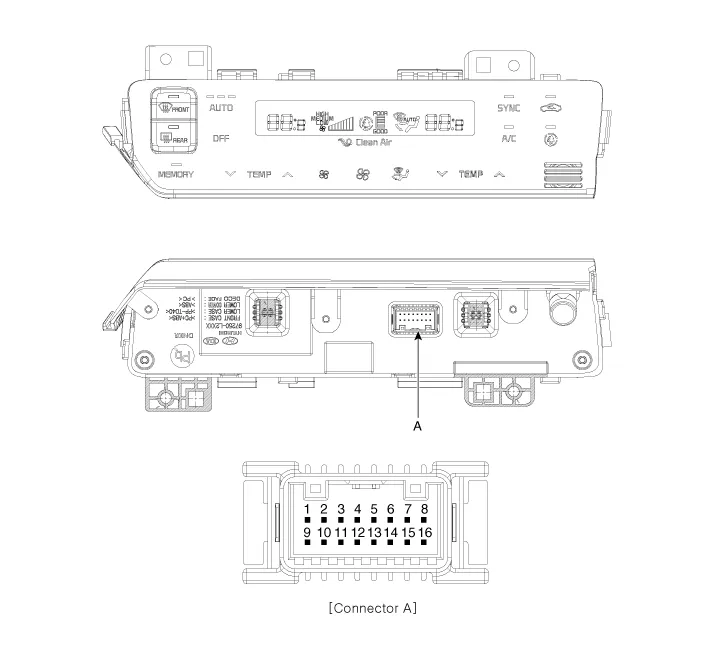
Connector
|
Pin NO |
Funtion |
Pin NO |
Funtion |
|
1 |
Ground |
9 |
Ground |
|
2 |
ILL- |
10 |
- |
|
3 |
- |
11 |
- |
|
4 |
- |
12 |
- |
|
5 |
HTD |
13 |
LIN BUS |
|
6 |
- |
14 |
ISG B+ |
|
7 |
ILL+ |
15 |
IGN2 |
|
8 |
IGN1 |
16 |
Battery (+) |
Repair procedures
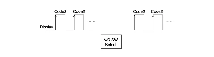
| Self Diagnosis |
| 1. |
Self-diagnosis process.
|


| 2. |
Fault code display
|


| Replacement |
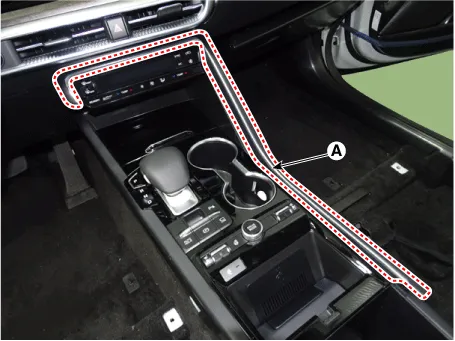
| 1. |
Disconnect the negative (-) battery terminal. |
| 2. |
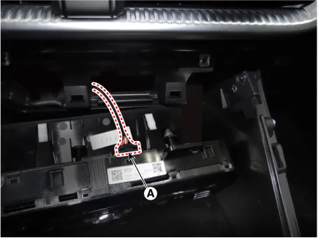
Using a screwdriver or remover, remove the floor console upper garnish (A).
|
| 3. |
Loosen the mounting screws and remove the A/C & heater controller unit (A).
|
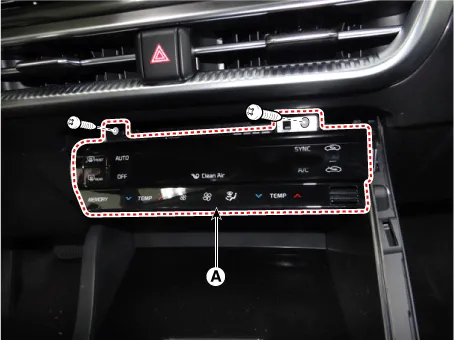
| 4. |
Disconnect the A/C & heater control connector (A).
|
| 5. |
To install, reverse the removal procedure.
|

Components and components location Components Connector Pin Function [Connector A] Pin NO Funtion Pin NO Funtion 1 Battery (+) 21 IGN2 2 ILL+ (TAIL) 22 IGN1 3 Sensor REF (+5V) 23 - 4 Mode Control Actuator Feedback 24 - 5 Temperature Actuator Feedback 25 - 6 Intake Actuator Feedback 26 - 7 EVAP Sensor (+) 27 - 8 AMB Sensor (+) 28 - 9 - 29 CAN High 10 Max Blower signal 30 CAN Low 11 Blower on signal 31 - 12 Temperature Control Actuator (Warm) 32 HTD (Rear Defrost) 13 Temperature Control Actuator (Cool) 33 P_CAN High 14 Intake Actuator (Recirculated Air) 34 P_CAN Low 15 Intake Actuator (Fresh Air) 35 - 16 Mode Control Actuator (Defrost) 36 - 17 Mode Control Actuator (Vent) 37 - 18 Sensor Ground 38 ECV+ 19 ILL - (RHEO) 39 ECV- (Ground) 20 Ground 40 Ground [Connector B] Pin NO Funtion Pin NO Funtion 1 Low 4 Middle Low 2 Common 5 Middle High 3 Ground 6 High Repair procedures Replacement 1.
Components and components location Components Connector Pin Function [Connector A] Pin NO Funtion Pin NO Funtion 1 Ground 11 Ground 2 Clean signal 12 - 3 Humidity 13 - 4 Diagnosis (Ionizer) 14 Driver Temperature Control Actuator Feedback 5 Ambient Temperature Sensor (+) 15 Passenger Temperature Control Actuator Feedback 6 Evaporator Temperature Sensor (+) 16 Intake Actuator Feedback 7 Right Photo Sensor (-) 17 Mode Control Actuator Feedback 8 Left Photo Sensor (-) 18 Auto Defogging Actuator Feedback 9 CAN Low 19 - 10 CAN High 20 - [Connector B] Pin NO Funtion Pin NO Funtion 1 Passenger Temperature Control Actuator (WARM) 11 - 2 Passenger Temperature Control Actuator (COOL) 12 - 3 Auto Defogging Actuator (CLOSE) 13 - 4 Auto Defogging Actuator (OPEN) 14 - 5 Driver Temperature Control Actuator (COOL) 15 - 6 Driver Temperature Control Actuator (WARM) 16 - 7 Intake Actuator (REC) 17 - 8 Intake Actuator (FRE) 18 Blower Motor (+) 9 Mode Control Actuator (DEF) 19 FET Drain Feedback 10 Mode Control Actuator (VENT) 20 FET (GATE) [Connector C] Pin NO Funtion Pin NO Funtion 1 Battery (+) 9 IGN1 2 IGN2 10 - 3 LIN BUS 11 - 4 Sensor REF (+5V) 12 - 5 - 13 - 6 ECV (+) 14 - 7 ECV (-) Ground 15 - 8 Ground 16 Sensor Ground Repair procedures Replacement 1.
Other information:
Kia Optima DL3 2019-2026 Service and Repair Manual: High Mounted Stop Lamp
Repair procedures Removal 1. Disconnect the negative battery terminal. 2. Remove the roof trim assembly. (Refer to Body - "Roof Trim Assembly") 3. Disconnect the high mounted stop lamp connector (A).
Kia Optima DL3 2019-2026 Service and Repair Manual: Rheostat
Schematic diagrams Connector and Terminal Function Repair procedures Removal 1. Disconnect the negative battery terminal. 2. Remove the crash pad lower panel. (Refer to Body - "Crash Pad Lower Panel") 3.
Categories
- Manuals Home
- Kia Optima Owners Manual
- Kia Optima Service Manual
- Floor Console Assembly
- Headlamps
- Identification Numbers
- New on site
- Most important about car
