Kia Optima DL3: Controller / Heater & A/C Control Unit (Manual)
Components and components location
| Components |
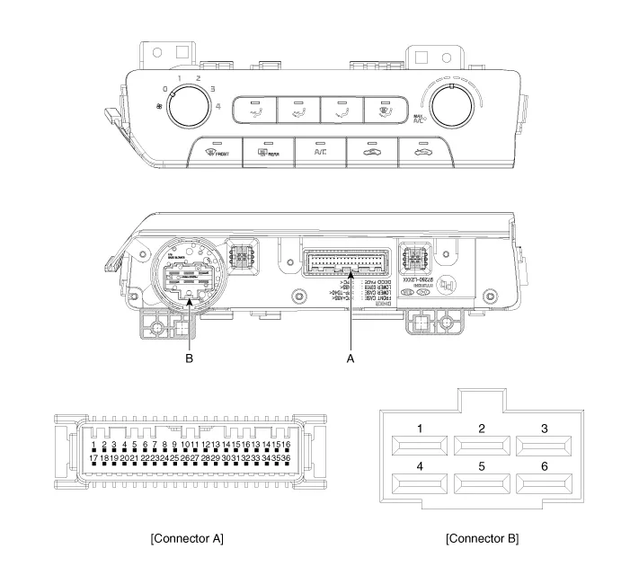
Connector Pin Function
[Connector A]
|
Pin NO |
Funtion |
Pin NO |
Funtion |
|
1 |
Battery (+) |
21 |
IGN2 |
|
2 |
ILL+ (TAIL) |
22 |
IGN1 |
|
3 |
Sensor REF (+5V) |
23 |
- |
|
4 |
Mode Control Actuator Feedback |
24 |
- |
|
5 |
Temperature Actuator Feedback |
25 |
- |
|
6 |
Intake Actuator Feedback |
26 |
- |
|
7 |
EVAP Sensor (+) |
27 |
- |
|
8 |
AMB Sensor (+) |
28 |
- |
|
9 |
- |
29 |
CAN High |
|
10 |
Max Blower signal |
30 |
CAN Low |
|
11 |
Blower on signal |
31 |
- |
|
12 |
Temperature Control Actuator (Warm) |
32 |
HTD (Rear Defrost) |
|
13 |
Temperature Control Actuator (Cool) |
33 |
P_CAN High |
|
14 |
Intake Actuator (Recirculated Air) |
34 |
P_CAN Low |
|
15 |
Intake Actuator (Fresh Air) |
35 |
- |
|
16 |
Mode Control Actuator (Defrost) |
36 |
- |
|
17 |
Mode Control Actuator (Vent) |
37 |
- |
|
18 |
Sensor Ground |
38 |
ECV+ |
|
19 |
ILL - (RHEO) |
39 |
ECV- (Ground) |
|
20 |
Ground |
40 |
Ground |
[Connector B]
|
Pin NO |
Funtion |
Pin NO |
Funtion |
|
1 |
Low |
4 |
Middle Low |
|
2 |
Common |
5 |
Middle High |
|
3 |
Ground |
6 |
High |
Repair procedures
| Replacement |
| 1. |
Disconnect the negative (-) battery terminal. |
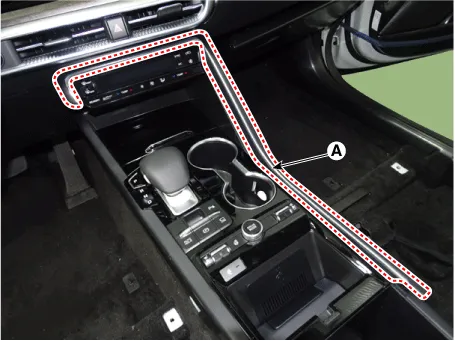
| 2. |
Using a screwdriver or remover, remove the floor console upper garnish (A).
|
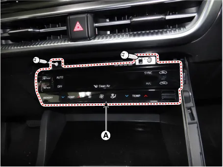
| 3. |
Loosen the mounting screws and remove the A/C & heater controller unit (A).
|
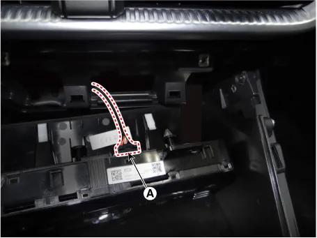
| 4. |
Disconnect the A/C & heater control connectors (A).
|
| 5. |
To install, reverse the removal procedure.
|

Components and components location Components Connector Pin NO Funtion Pin NO Funtion 1 Ground 9 Ground 2 ILL- 10 - 3 - 11 - 4 - 12 - 5 HTD 13 LIN BUS 6 - 14 ISG B+ 7 ILL+ 15 IGN2 8 IGN1 16 Battery (+) Repair procedures Self Diagnosis 1.
Other information:
Kia Optima DL3 2019-2026 Service and Repair Manual: Wiper Motor
Schematic diagrams Connector and Terminal Function Pin Function 1 Ground (-) 2 Parking 3 Power (+) 4 Low 5 High Repair procedures Remova
Kia Optima DL3 2019-2026 Service and Repair Manual: Climate Control Air Filter
Description and operation Description The climate control air filter is located in the blower unit. It eliminates foreign materials and odor. The particle filter performs a role as an odor filter as well as a conventional dust filter to ensure comfortable interior environment.
Categories
- Manuals Home
- Kia Optima Owners Manual
- Kia Optima Service Manual
- Suspension System
- Rear Brake Disc
- Cooling System
- New on site
- Most important about car
