Kia Optima DL3: Controller / Heater Control Unit
Kia Optima DL3 2019-2026 Service and Repair Manual / Heating, Ventilation and Air Conditioning / Controller / Heater Control Unit
Components and components location
| Components |

| Connector Pin Function |
[Connector A]
|
Pin NO |
Funtion |
Pin NO |
Funtion |
|
1 |
Ground |
11 |
Ground |
|
2 |
Clean signal |
12 |
- |
|
3 |
Humidity |
13 |
- |
|
4 |
Diagnosis (Ionizer) |
14 |
Driver Temperature Control Actuator Feedback |
|
5 |
Ambient Temperature Sensor (+) |
15 |
Passenger Temperature Control Actuator Feedback |
|
6 |
Evaporator Temperature Sensor (+) |
16 |
Intake Actuator Feedback |
|
7 |
Right Photo Sensor (-) |
17 |
Mode Control Actuator Feedback |
|
8 |
Left Photo Sensor (-) |
18 |
Auto Defogging Actuator Feedback |
|
9 |
CAN Low |
19 |
- |
|
10 |
CAN High |
20 |
- |
[Connector B]
|
Pin NO |
Funtion |
Pin NO |
Funtion |
|
1 |
Passenger Temperature Control Actuator (WARM) |
11 |
- |
|
2 |
Passenger Temperature Control Actuator (COOL) |
12 |
- |
|
3 |
Auto Defogging Actuator (CLOSE) |
13 |
- |
|
4 |
Auto Defogging Actuator (OPEN) |
14 |
- |
|
5 |
Driver Temperature Control Actuator (COOL) |
15 |
- |
|
6 |
Driver Temperature Control Actuator (WARM) |
16 |
- |
|
7 |
Intake Actuator (REC) |
17 |
- |
|
8 |
Intake Actuator (FRE) |
18 |
Blower Motor (+) |
|
9 |
Mode Control Actuator (DEF) |
19 |
FET Drain Feedback |
|
10 |
Mode Control Actuator (VENT) |
20 |
FET (GATE) |
[Connector C]
|
Pin NO |
Funtion |
Pin NO |
Funtion |
|
1 |
Battery (+) |
9 |
IGN1 |
|
2 |
IGN2 |
10 |
- |
|
3 |
LIN BUS |
11 |
- |
|
4 |
Sensor REF (+5V) |
12 |
- |
|
5 |
- |
13 |
- |
|
6 |
ECV (+) |
14 |
- |
|
7 |
ECV (-) Ground |
15 |
- |
|
8 |
Ground |
16 |
Sensor Ground |
Repair procedures
| Replacement |
| 1. |
Disconnect the negative (-) battery terminal. |
| 2. |
Remove the glove box. (Refer to Body - "Glove Box") |
| 3. |
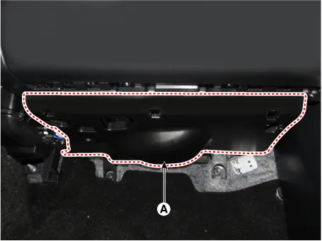
Remove the crash pad under cover (A).
|
| 4. |
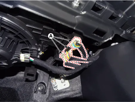
Disconnect the heater controller unit connectors (A).
|
| 5. |
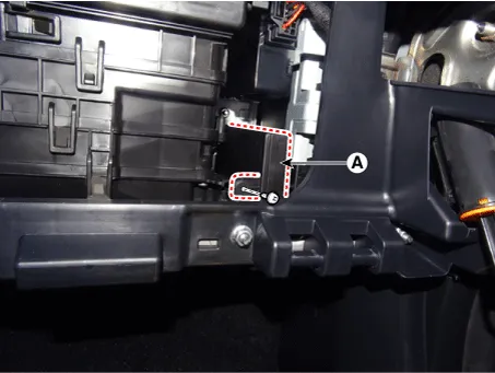
After loosening the mounting screw, remove the heater controller unit (A).
|
| 6. |
To install, reverse the removal procedure.
|
