Kia Optima DL3: Seat Electrical / Power Seat Motor
Components and components location
| Components |
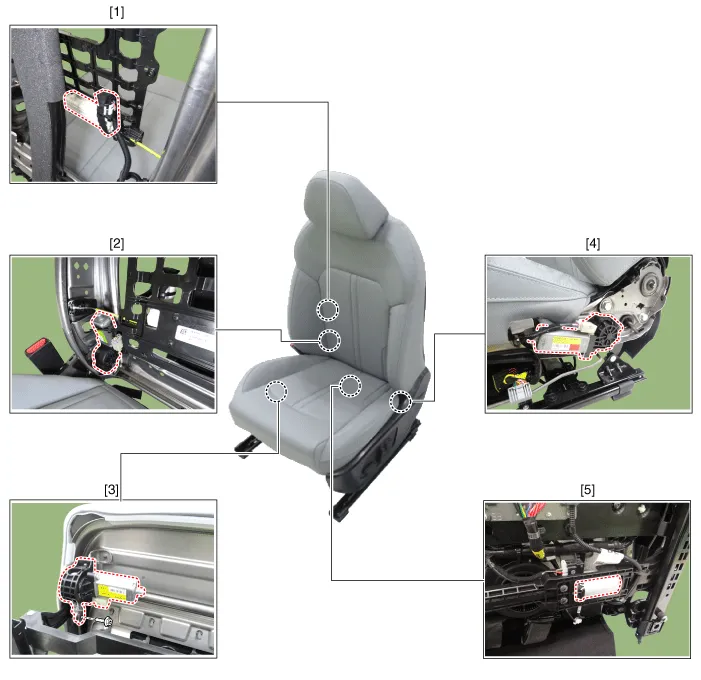
| 1. Lumbar support motor 2. Reclining motor 3. Front height motor |
4. Rear height motor 5. Slide motor |
Repair procedures
| Inspection |
| 1. |
Disconnect the negative battery terminal. |
| 2. |
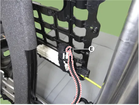
Disconnect the motor connector after removing the seat. A : Front height motor
B : Slide motor
C : Rear height motor
D : Reclining motor
E : Lumbar support motor
|
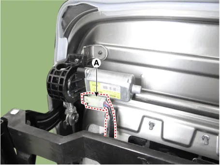
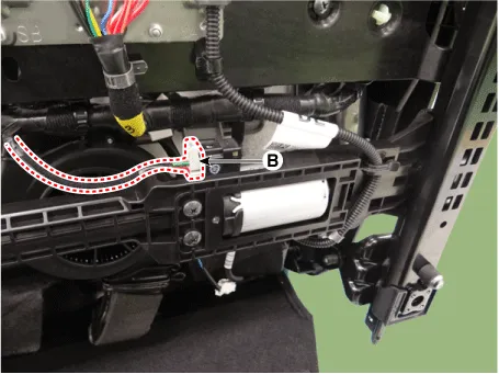
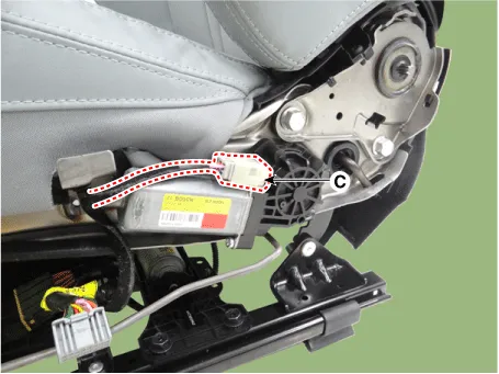
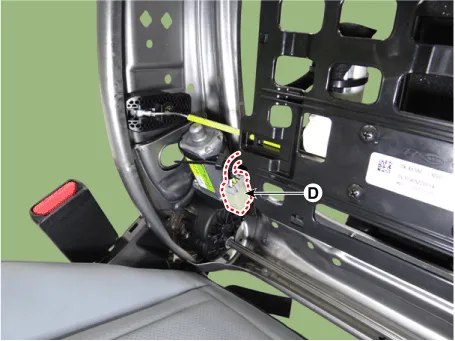
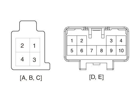
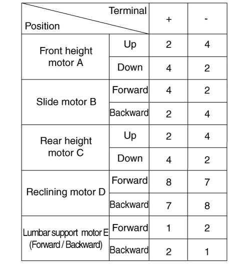
| 3. |
When the battery power is supplied to the motor connector, check the motor for smooth operation.
|
Repair procedures Removal 1. Remove the front seat shield outer cover. (Refer to Body - "Front Seat Shield Outer Cover") 2.
Components and components location Component Location 1. Walk-in switch Repair procedures Removal When prying with a flat-tip screwdriver or use a prying trim tool, wrap it with protective tape, and apply protective tape around the related parts, to prevent damage.
Other information:
Kia Optima DL3 2019-2026 Service and Repair Manual: Washer Motor
Repair procedures Inspection Washer Motor 1. With the washer motor connected to the reservoir tank, fill the reservoir tank with water. Before filling the reservoir tank with water, check the filter for foreign mat
Kia Optima DL3 2019-2026 Service and Repair Manual: A/C Pressure Transducer
Description and operation Description The A/C Pressure Transducer (APT) converts the pressure value of high pressure line into voltage value after measuring it. By converted voltage value, engine ECU controls the cooling fan by operating it high speed or low speed.
Categories
- Manuals Home
- Kia Optima Owners Manual
- Kia Optima Service Manual
- Timing Chain
- Engine Mechanical System
- Battery
- New on site
- Most important about car
