Kia Optima DL3: Body (Interior and Exterior) / Inside Rear View Mirror
Components and components location
| Component Location |

| 1. Inside rear view mirror
|
Repair procedures
| Replacement |
Put on gloves to prevent hand injuries. |

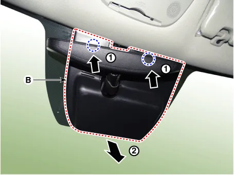
| 1. |
Remove the multifunction sensor cover (A), (B).
|
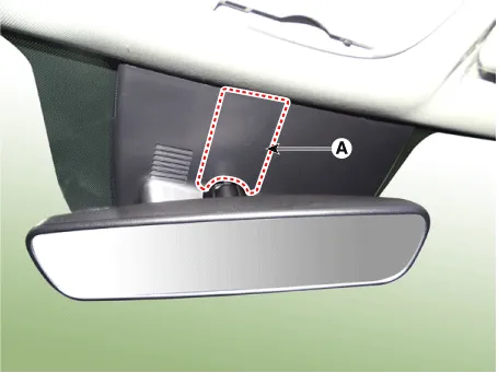
| 2. |
Disconnect the ECM mirror connector (A).
|
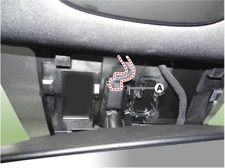
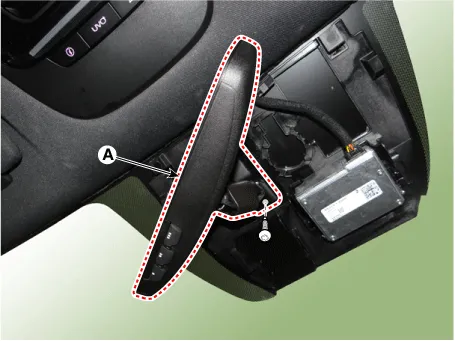
| 3. |
Loosen the mounted screws and push the ECM mirror base upward to remove the ECM mirror assembly (A).
|
| 4. |
To install, reverse the removal procedure.
|

Components and components location Component Location 1. Outside rear view mirror Repair procedures Replacement Put on gloves to prevent hand injuries.
Components and components location Component Location 1. Cowl top cover Repair procedures Replacement • When removing with a flat-tip screwdriver or remover, wrap protective tape around the tools to prevent damage to components.
Other information:
Kia Optima DL3 2019-2026 Service and Repair Manual: Mood Lamp Unit
Schematic diagrams Connector and Terminal function Repair procedures Removal When removing with a flat-tip screwdriver or remover, wrap protective tape around the tools to prevent damage to components.
Kia Optima DL3 2019-2026 Service and Repair Manual: Smart Key Unit
Schematic diagrams Connector and Terminal Function Pin Function Connector A Connector B Connector C Connector D 1 - Front washer switch (Output) - Driver outside handle switch (Input)
Categories
- Manuals Home
- Kia Optima Owners Manual
- Kia Optima Service Manual
- Body Electrical System
- Engine Mechanical System
- Engine Control / Fuel System
- New on site
- Most important about car
