
Kia Optima DL3: Audio/AVN System / Multimedia Jack
Schematic diagrams
| Circuit Diagram |
| Audio |
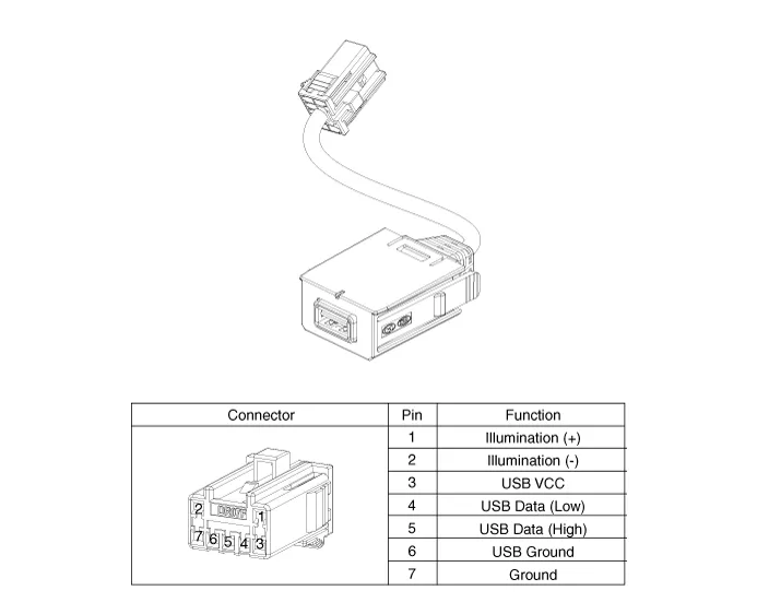
| Display Audio / AVN |
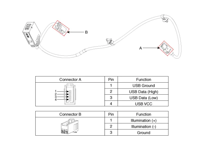
Repair procedures
| Removal |
| 1. |
Disconnect the negative battery terminal. |
| 2. |
Remove the main crash pad assembly. (Refer to Body - "Main Crash Pad Assembly") |
| 3. |
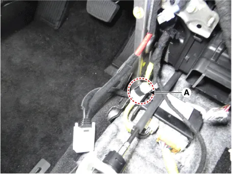
Disconnect the multimedia jack connector (A).
|
| 4. |
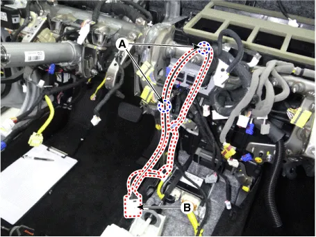
Remove the multimedia wiring jack (B) after removing the fixing fasteners (A).
|
| Installation |
| 1. |
Install in the reverse order of removal. |
Components and components location Components 1. Left remote control switch (Audio + Bluetooth + Voice) 2. Right remote control switch (Trip + SCC + LFA) Schematic diagrams Circuit Diagram [Audio + Bluetooth + Voice] [Trip + SCC + LFA] Repair procedures Removal 1.
Repair procedures Inspection 1. Remove the overhead console lamp. (Refer to Lighting System - "Overhead Console Lamp") 2.
Other information:
Kia Optima DL3 2019-2026 Service and Repair Manual: Integrated Memory Seat (IMS) Switch
Schematic diagrams Connector and Terminal Function Repair procedures Removal When prying with a flat-tip screwdriver or use a prying trim tool, wrap it with protective tape, and apply protective tape around the related parts, to prevent dam
Kia Optima DL3 2019-2026 Service and Repair Manual: Headlamps
Components and components location Component Location 1. Low beam 2. High beam 3. Daytime Running Light / Position lamp 4. Low assist beam 5. Turn signal lamp Schematic diagrams Connector and Terminal Function Connector Terminal Function
Categories
- Manuals Home
- Kia Optima Owners Manual
- Kia Optima Service Manual
- Emergency trunk safety release
- Floor Console Assembly
- Air bag collision sensors
- New on site
- Most important about car
