NO
|
Ref Symbol
|
Name
|
Color
|
Signal input
|
Signal Control
|
Check point
|
1
|
|
Turn signal (Left)
|
Green
|
CAN
|
ICU
(Gateway)
|
1) Multifunction Switch
2) ICU
3) CAN Failure
|
2
|

|
Turn signal (Right)
|
Green
|
CAN
|
ICU
(Gateway)
|
1) Multifunction Switch
2) ICU
3) CAN Failure
|
3
|

|
Tail Lamp
|
Green
|
CAN
|
ICU
(Gateway)
|
1) Multifunction Switch
2) ICU
3) CAN Failure
|
4
|

|
Front Fog Lamp
|
Green
|
CAN
|
ICU
(Gateway)
|
1) Multifunction Switch
2) ICU
3) CAN Failure
|
5
|

|
Rear Fog Lamp
|
Yellow
|
CAN
|
ICU
(Gateway)
|
1) Multifunction Switch
2) ICU
3) CAN Failure
|
6
|

|
High Beam
|
Blue
|
CAN
|
ICU
(Gateway)
|
1) Multifunction Switch
2) ICU
3) CAN Failure
|
7
|

|
Low Beam
|
Green
|
CAN
|
ICU
(Gateway)
|
1) Multifunction Switch
2) IBU
3) CAN Failure
|
8
|

|
LED Headlamp
|
Yellow
|
CAN
|
AFS
|
1) AFS System
2) CAN Failure
|
9
|
|
Warning
|
Yellow
|
CAN
|
TPMS
|
1) TPMS System
2) CAN Failure
|
ICU
|
1) Exterior Lamp
2) IBU
3) CAN Failure
|
Yellow
|
Hard-wired
|
Low Washer
|
1) Washer fluid level sensor
2) Wiring Failure
|
Digital Input
|
Reminder for service checks
|
10
|
|
Battery Charge
|
Red
|
Hard-wired
|
Alternator
|
1) Alternator
2) Wiring Failure
3) Battery
|
11
|
|
Oil Pressure
|
Red
|
Hard-wired
|
ECM
|
1) Oil Pressure Sensor
2) Wiring Failure
3) ECM
4) CAN Failure
|
12
|
|
Check Engine
|
Yellow
|
CAN
|
ECM
|
1) ECM
2) CAN Failure
|
13
|
|
Immobilizer
|
Yellow
|
CAN
|
IMMOBILIZER
SMK
|
1) Immobilizer System
2) IBU
3) CAN Failure
4) Hard-wired
|
14
|
|
Parking Brake
Brake Fluid
EBD
EPB
EVP
|
Red
|
CAN
|
ICU
(Gateway)
EBD
EPB
EVP
ABS
TCS
|
1) IBU
2) ABS System
3) EPB System
4) CAN Failure
5) Parking Brake Switch
6) Brake Oil Lever Sensor
|
15
|

|
ABS
|
Yellow
|
CAN
|
ABS
|
1) ABS System
2) CAN Failure
|
16
|
|
ESC
|
Yellow
|
CAN
|
TCS
|
1) ABS System
2) CAN Failure
|
17
|

|
ESC Off
|
Yellow
|
CAN
|
TCS
|
1) ABS System
2) CAN Failure
|
18
|

|
EPB
|
Yellow
|
CAN
|
EPB
|
1) EPB System
2) CAN Failure
|
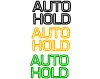
19
|
|
Auto Hold
|
White
Yellow
Green
|
CAN
|
VDC
|
1) TCS System
2) CAN Failure
|
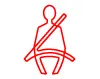
20
|
|
Seat Belt
|
Red
|
CAN
|
ICU
(Gateway)
|
1) ICU
2) CAN Failure
|
21
|

|
Airbag
|
Red
|
CAN
|
SRSCM
|
1) SRSCM System
2) CAN Failure
|
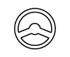
22
|

|
EPS
(MDPS)
|
Red
|
CAN
|
MDPS
|
1) MDPS Unit System
2) MDPS Motor
3) CAN Failure
|
23
|

|
HDA
|
White
Green
|
CAN
|
MFC
|
1) HDA System
2) CAN Failure
|
24
|

|
TPMS
|
Yellow
|
CAN
|
TPMS
|
1) TPMS System
2) TPMS Sensor
3) CAN Failure
|
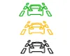
25
|
|
LKA
|
White
Yellow
Green
|
CAN
|
LKA
|
1) LKA System
2) CAN Failure
|
26
|
|
Fuel Warning
|
Yellow
|
Direct
(Micom)
|
Fuel Sender
|
1) Fuel Sender Failure
2) Wiring Failure
|
27
|

|
ECO
|
Green
|
Hard-wired
|
ECO Mode
|
1) Drive Mode Switch
2) ECM System
3) TCU System
|
28
|

|
SPORT
|
Yellow
|
Hard-wired
|
SPORT Mode
|
1) Drive Mode Switch
2) ECM System
3) TCU System
|
29
|

|
CRUISE
|
Green
|
CAN
|
ECM
|
1) ECM
2) CAN Failure
|
30
|
|
FCA
|
Yellow
|
CAN
|
MFC
SCC
|
1) MFC System
2) SCC Failure
3 CAN Failure
|
31
|
|
AUTO STOP
|
Green
Yellow
|
CAN
|
ECM
|
1) ECM System
2) CAN Failure
|